> It weighed too much for three reasons. The pattern was made by hand
> and it
> is near impossible to make a large pattern with .1875" consistent
wall
> thickness
> by hand even if you are a HIGHLY skilled pattern maker. I know I have
> made some
> intake manifold patterns. An accurate pattern made on a NC mill
> profoundly changes all that.
>
> The second factor is what can the foundry do in terms of minimum wall
> thickness? American International in San Fernando California has no
> problem with that as I have seen hundreds of parts in their foundry.
>
> The third factor was the incorporation of motor mounts in the bell
> housing.
> That idea has fallen into dis favor as the preferred method of
engine
> mounting is the Schertz beam.
>
> The projected weight of this bell housing, as cast, is one pound
lighter
> than your set up despite a conservative wall thickness of .2 inches.
> That is before NC machining where more weight can be removed.
>
> As far as the load is concerned we have already done some static
> testing thanks
> to Jerry Hey. We will do the same kind of static testing on the new
> bell housing
> as well as an FEA.
>
> Not many new designs are mounting the starter at 6 O'clock as it
> precludes using one large rad under the engine which simplifies the
> cooling plumbing and the ducting. Mounting the starter at six
O-clock
> allows a
> simplification of the bell housing and a reduction in its weight and
> cost.
>
> Paul Lamar ...No rotor no motor.
>
> Opss correction.
>
> That should be: "Mounting the starter at nine O-clock allows a
> simplification of the bell housing and a reduction in its weight and
> cost."
>
I don't really understand your comment about the starter at 6 o'clock
precluding positioning the rad under the engine.
That is the configuration I have. In my pusher config, the rad is below
and forward of the starter. In the future, to lower drag, I would like
to position it even farther forward.
In the photos on this page, that you took at Arlington last year, you
can see the starter bump in the cowl is way above the rad. The rad is
forced to that low position by the oil pan, not the starter. You can
also see my concept 3D drawing, where I would like to position the rad
farther forward.
http://www.bridgingworlds.com/LEZ13B/LEZ13B.htm
Perry
I was speaking of a tractor installation Perry where the air comes
in over
the top of the rad to keep it cool. Your cowling is so tight I think you
would have a bump where ever you put the starter.
If you still have Rhino working send me an IGES zipped of the last 3D
and I will do some scale transparent renderings with the starter in
various positions.
Paul Lamar ...No rotor no motor.
Paul,
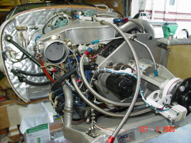
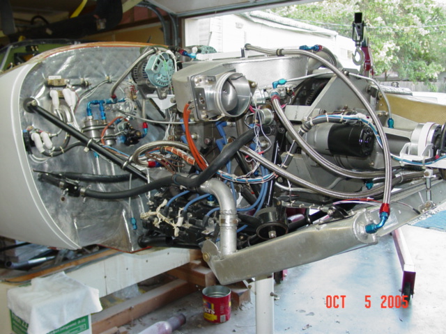
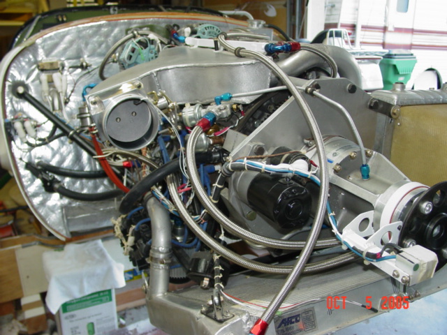
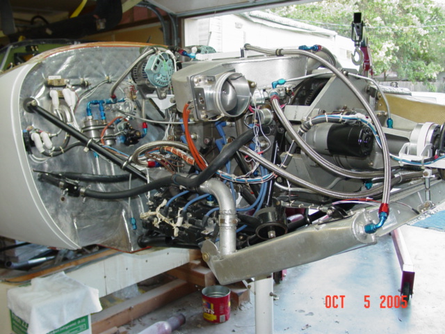
My installation shows why the starter had to be relocated. The nose
gear is integrated into the motor mount, and is near the front of the
mount. There are gear supports behind the nose strut that prevent the
radiator from fitting there. Moving the starter to the 9 o'clock
position freed up just enough space to fit the radiator in front of the
nose strut.
Mark St.
You did a beautiful job Mark. Your airplane is right up there with Bulent's
and Al Gietzen's. All three of you guys could win the Sun & Fun best auto engine
award if you choose to fly in there some year.
BTW Larry tells me the new bell housing pattern will be done in about a week.
We should have some pictures then.
Paul Lamar ...No rotor no motor.
The Rotary Engine NewsLetter. Powered by Linux.
ACRE NL web site.
http://www.rotaryeng.net
Copyright 1998-2006 All world wide rights reserved.