> C&R built mine from drawings I sent them. The tanks are about 2"
thick
> and the cores are standard, I think 1.25" thick. Might be metric.
> This would make the space between the two cores approx. 0.75".
>
> Perry
>
> When did you send them dwgs Perry? I know it is in the airplane
> but did you take any pictures before you put it in there?
>
> Paul Lamar ...No rotor no motor.
I installed the psru and prop December 2004. I knew I need more rad
since I was developing more power, but it was fine for the winter. I
ordered the new rad early 2005. I sent them the 3D view that you have,
with overall dimensions of 13.5 inches wide by 17.5 inches long. The
ports are 1" NPT, on the right side forward faces of the dual tanks at
the front. Ideal for connecting to the waterpump, as shown on the page
http://www.bridgingworlds.com/LEZ13B/LEZ13B.htm. I know it took them a
couple months to get started on it, they said they were busy. By
April-May 2005 I had to call them a few times to get it moving, as I
wanted it installed for summer flying. I think I received it by May 17
2005 because I have a sketch drawing with that date (screen capture
attached), showing how I had to make the inlet ramp much longer, and
move the rad aft, because the overall rad thickness increased from 2" to
4". Unfortunately I didn't take any photos at the time, I was in a bit
of a rush to get it installed because of the warm weather and a trip to
Kansas July 2005. That was the last engine install mod made, pretty much
just been flying it ever since, only maintenance now. 660TT, 500SMOH.
Perry
Ah Ha so that is where they got it :)
Paul Lamar ...No rotor no motor.
My memory is slowly coming back. The guy I talked to there at the time
(early 2005) already knew of the concept, and correctly called it a
cross counter flow rad. So I assume they have made them before that time
for other applications.
Perry
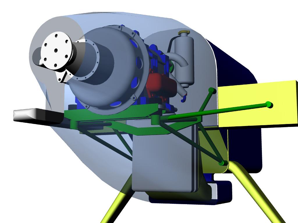
Here is a 3D of the cowl with the small spinner Perry.
I guessed the diameter of the spinner at about 10 inches.
Have you considered taping some tufts on the lower back of the cowl
and have a buddy fly along side and take pictures with
a telephoto lens. Perhaps it slopes up too fast.
A larger spinner would give you more room for starters :)
Klaus is always fooling with the lower part of his cowl
cowl back there. It appears to be a problem area
for drag. His latest comes to a narrow vertical panel.
A slot there would be a good place to dump the hot cooling air.
------------------------------------------
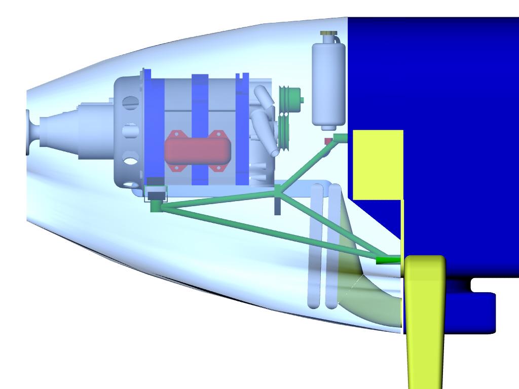
Here is the side view.
------------------------------------
Here it is with less up slope on the bottom. In theory a bit less
drag. The drawback to mounting the rads like this is it precludes
laterally bracing the lower space frame motor mount bay within the bay itself
using diagonals or an X. It becomes necessary to brace the motor mount laterally
with a removable strut over to one side of the spar or the other.
The previous scheme for mounting the cross counter flow rad would
still work with this cowl.
It quite obvious a rotary mounted in a Long EZ has a lower drag cowl than
a Lyc or Continental. Probably a bit more lift in the bargain as the wing
root is not compromised by the cowl.
Paul Lamar ...No rotor no motor.
The Rotary Engine NewsLetter. Powered by Linux.
ACRE NL web site.
http://www.rotaryeng.net
Copyright 1998-2006 All world wide rights reserved.