Thanks..
I'll bet the exit is in a region of reasonably thick boundary layer. If
so, the flow on the surface may be very slow or even reversed in places
- leading to relatively high exit pressures and low flow through the
cooler. I think making the exit lip taller should help things, though
not pretty. Like a Gurney Flap, or the cowl exhaust on an older Cessna..
Matt-
--------------
Matt;
My little boundary layer program says the BL at the exit position (not
considering the effects of the fairing) would be about 0.8"
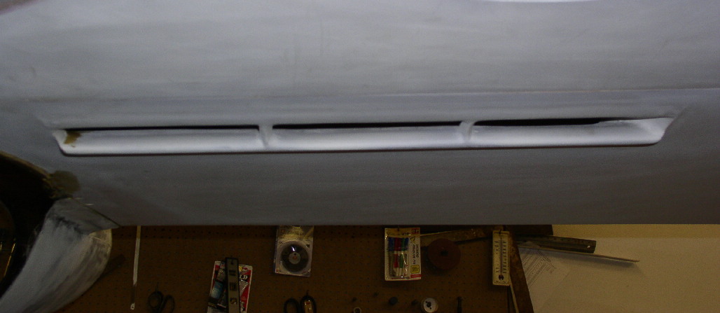
One of the photos that Paul posted (first photo) is my original
configuration - just a curved ramping up to the exit. This never flew
because an "expert" told me that it would create a lot of turbulence and
drag - that a better approach would be an airfoil shape that would be the
flow attached. This supposedly would provide lower pressure at the exit
and would also provide more spacing internally from the exit face of the
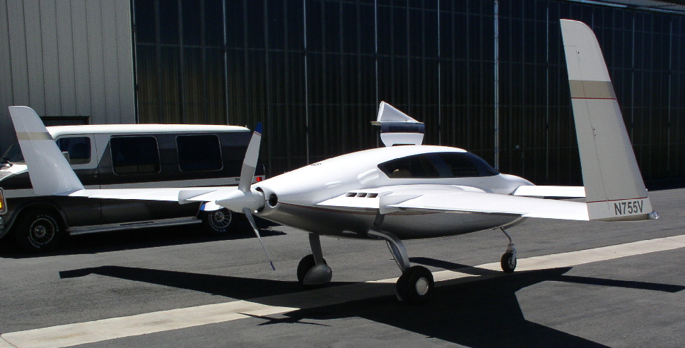
core. Convinced; I re-did the fairing as shown in the second photo.
Based on the theory of low pressure above at the exit, and high pressure
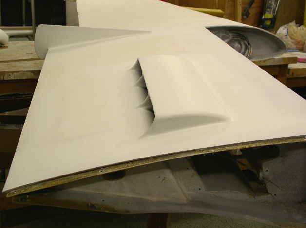
below at the entrance, not much of a scoop was put at the entrance; just an
airfoil shaped lip that extended below the surface about 1/2" (photo 3).
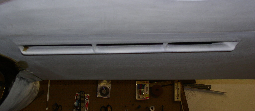
The oil cooler, and second coolant rad are in the wing root behind the
strakes (photo 4)
Early flights showed the setup was not effective. (BTW; custom oil cooler
core dimensions of 5.5" x 21.5" x 3.3" thick.) It seemed the most expedient
solution was to make the inlet into more of a ram scoop, which I did
initially with a temporary metal extension, the photo that Paul attached
earlier. This improved things enough to allow flight testing to proceed. I
then replaced it with a nicely glassed scoop of similar configuration (1.25"
x 23" wide, sorry, no photo) and as we went into cooler winter weather; all
was fine.
This scoop does ingest the boundary layer, but if it's overall effectiveness
is better than 65%, it should provide the necessary air flow. I have place
some VGs forward of the entrance to reduce BL effects.
I have managed to get tubes in place to measure pressure before and after
the core to measure pressures there, and will then move them to get
pressures at the entrance and exit. It'll be a few days before I have a
chance to get data.
I thought just cutting the exit fairing shorter would help, so I cut the
center section of the fairing back about 3" to see if it would help. No
detectable difference in the temperatures. I have also tried VGs on the
upper surface of the exit fairing to no avail. Perhaps VGs further forward
on the strake?
The other wing has a second parallel coolant radiator still with the
original inlet (no scoop), and it does very little cooling. But it is
interesting that the in-cowl rad with sort of p-51 style armpit scoop,
handles the cooling just fine - total core volume of about 400 cu. in.
Sorry to gone on here, but I appreciate any help I can get. A solution
(with minimal structure changes, of course) is necessary.
Al
The Rotary Engine NewsLetter. Powered by Linux.
ACRE NL web site.
http://www.rotaryeng.net
Copyright 1998-2006 All world wide rights reserved.