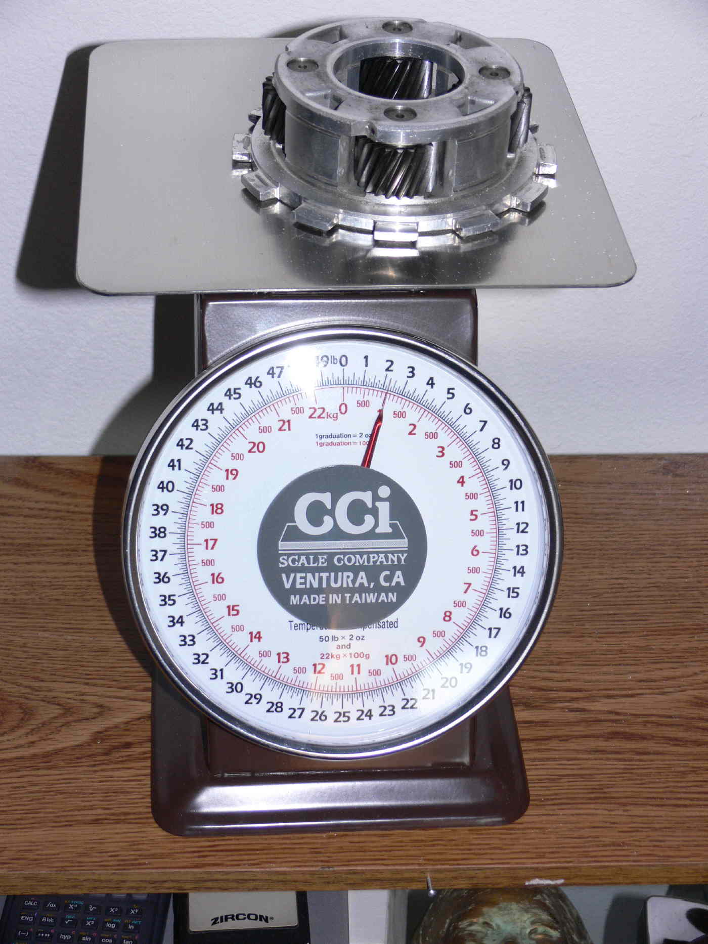
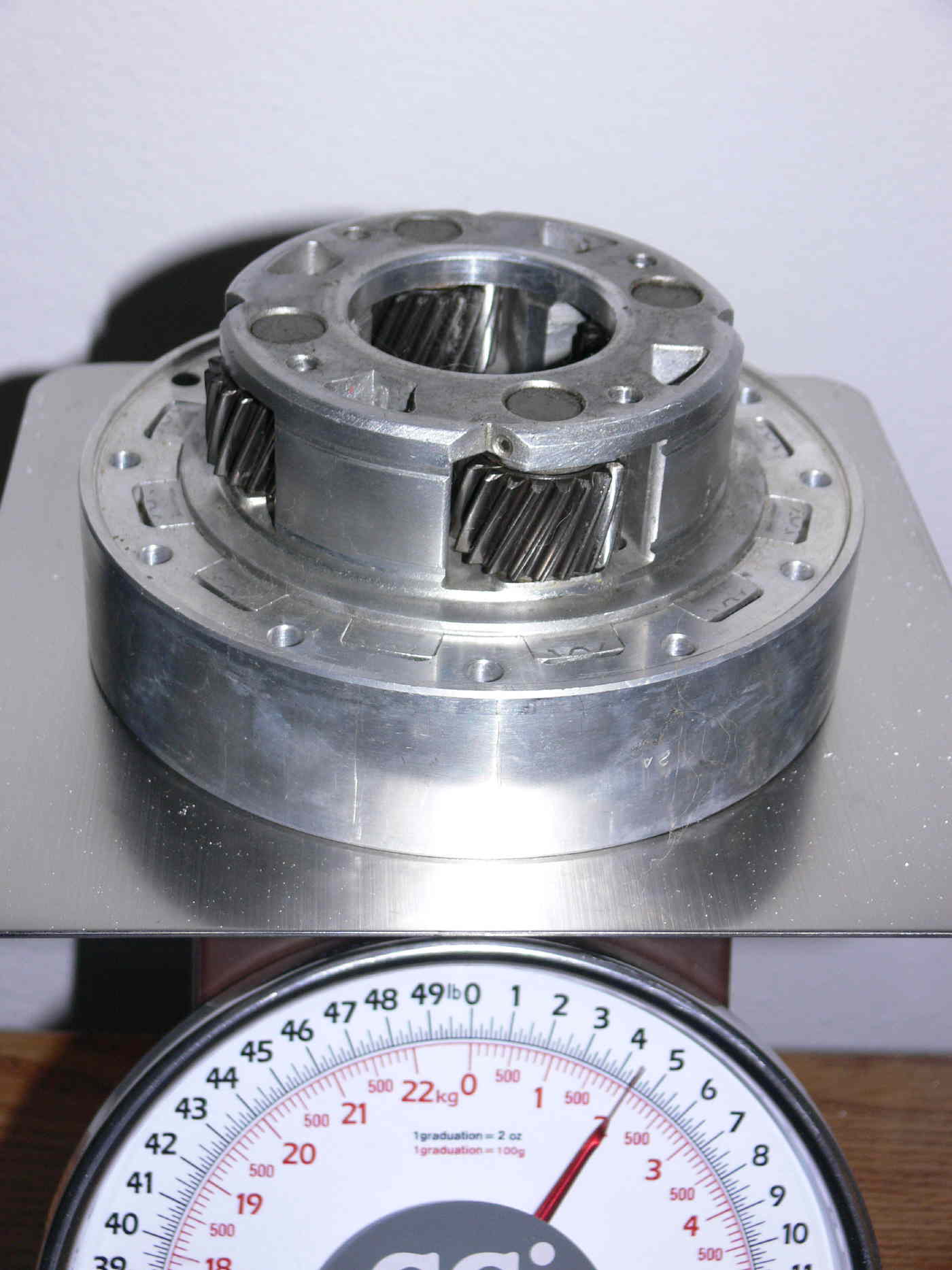
Here is a strain gauge setup.
TD93A indicator and ZFLA-1-11 foil gage.
The combination indicator and foil gauge is temperature compensated
from
+10C to +100C.
The URL below will take you to the indicator page. On the left side of
the screen you can click on the Strain Gage Series List box. That will
take you to the strain gauge page. The ZFLA-1-11 specs are there
toward
the bottom. From the indicator page, clicking on the Integral Lead
Wire
box will take you to a page that shows the strain gage and wires
already
connected. Just glue the strain gage to the metal under stress, route
the wire, plug it in and you are ready to go.
This web site also lists the appropriate adhesives.
The only fly in the ointment is the need for 60Hz power, which is no
problem for a test stand dyno but would be if you wanted to measure
torque/HP in the air. For in the air measurements a 100W inverter will
serve as the indicator only draws 60W.
The URL for the instrument is;
http://straingage.com/instrument/instrument_sub/TD93A.PHP
Doc Custer
Retired Software Engineer and sometime Audiologist
That is not the only fly :)
The part under stress is this shaft. How do you get the data
out of the rotating strain gage mounted on the shaft to a stationary
signal conditioner?
--
Paul Lamar ...No rotor no motor.
You put the strain gage on a stationary part that is resisting the reaction
force. I am not familiar with the exact setup of the planetary gears. If the
ring gear is stationary, you attach the strain gage to one of the bosses
that prevent the ring gear from rotating. If the planet carrier is
stationary, you attach the strain gage to one of the carrier bosses that
prevent the carrier from rotating.
Doc Custer
Retired Software Engineer and sometime Audiologist
-
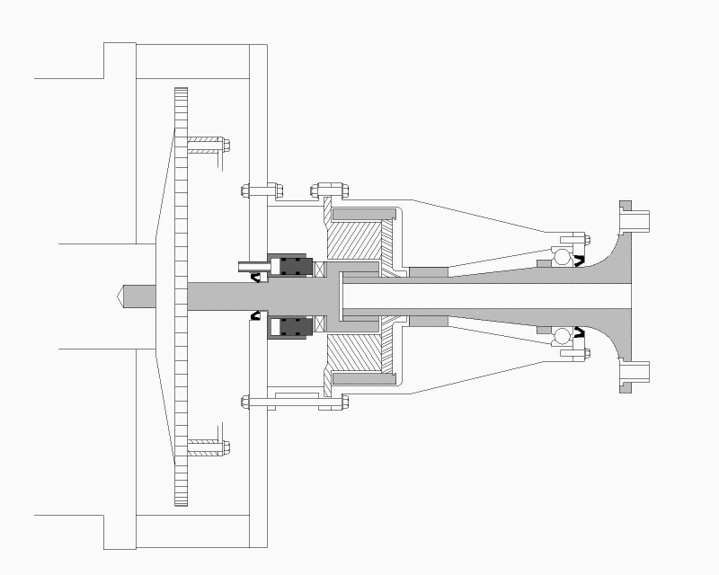
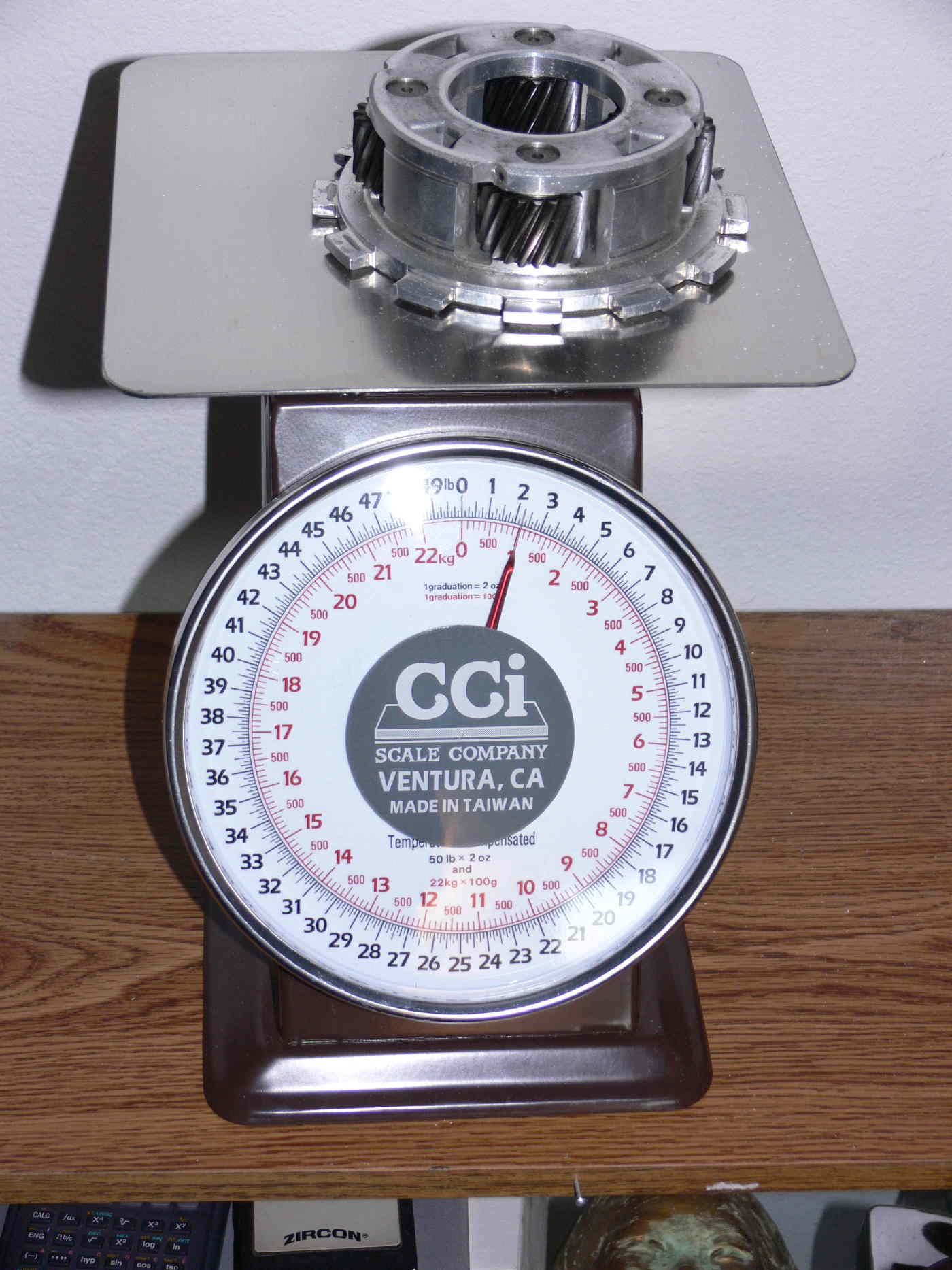
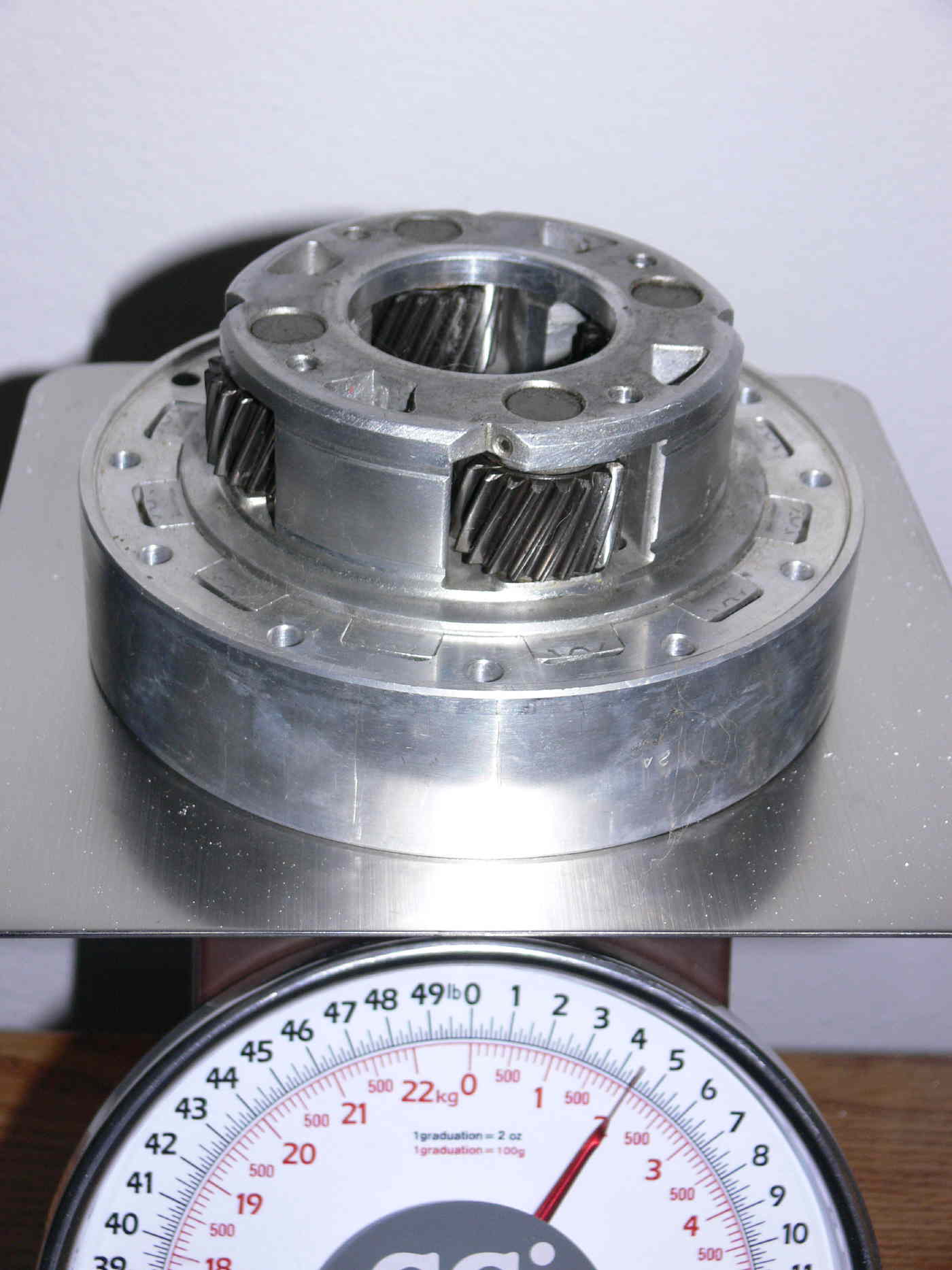
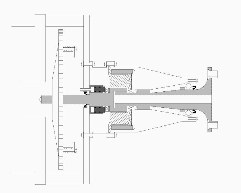
Here is a pretty good dwg and some pictures. Mark a suggested position
with xpaint and send it back. The half inch plate behind the thrust
bearing is out as it is subject to complicated forces from the the prop
depending on the pitch or yaw rate of the aircraft. This is the 2.17:1
box. The 2.85:1 ring gear is pressed into the housings and locked
with a few keyways.
I'll also repeat Matt's question. What is wrong with the low cost hydraulic cylinder
solution? Do you want a electrical signal that can be fed into a computer?
Perhaps and annular load cell would work to measure the helical gear
thrust. Load cells are not low cost.
--
Paul Lamar ...No rotor no motor.
The Rotary Engine NewsLetter. Powered by Linux.
ACRE NL web site.
http://www.rotaryeng.net
Copyright 1998-2006 All world wide rights reserved.