Here is a pretty good dwg and some pictures. Mark a suggested position
with xpaint and send it back. The half inch plate behind the thrust
bearing is out as it is subject to complicated forces from the the prop
depending on the pitch or yaw rate of the aircraft. This is the 2.17:1
box. The 2.85:1 ring gear is pressed into the housings and locked
with a few keyways.
I'll also repeat Matt's question. What is wrong with the low cost
hydraulic cylinder
solution? Do you want a electrical signal that can be fed into a computer?
Perhaps and annular load cell would work to measure the helical gear
thrust. Load cells are not low cost.
--
Paul Lamar ...No rotor no motor.
Paul,
How do you transpose the sungear thrust into Torque/HP?
Having numbers of needle thrust bearings to take-up the thrust loads, does
this diminish the total thrust load on the annular, or merely share the load
through each of the thrust bearing.
George ( down under)
The load on the annular cylinder is not changed. Both have the same load.
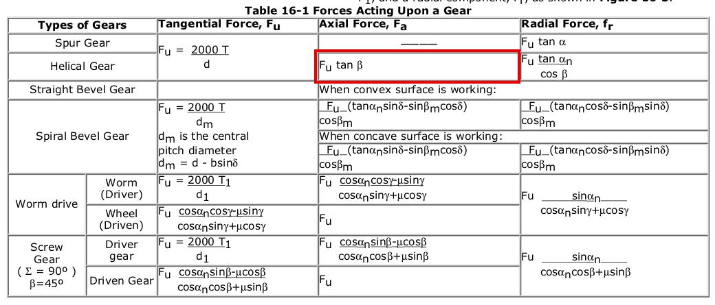
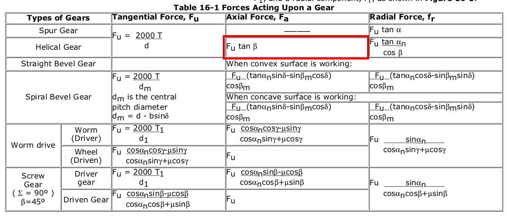
T is torque in inch pounds and "d" is gear pitch line diameter.
Figure the tangential force Fu in pounds and plug that into the equation for axial force.
Beta is the angle of the gear tooth. As I recall it is about 37 degrees.
The angle might be in radians. One radian is 57.295 degrees.
It is about 200 or so pounds as I recall.
You then must calibrate it with a torque wrench. X amount of torque
results in Y pressure on the gage. It is a linear relationship.
Paul Lamar ...No rotor no motor.
The Rotary Engine NewsLetter. Powered by Linux.
ACRE NL web site.
http://www.rotaryeng.net
Copyright 1998-2006 All world wide rights reserved.