OK, all you aerodynamicists; here?s the scoop ? what I did and what I
measured;
1 ? sealed the strake/wing in front of exit fairing - - No effect
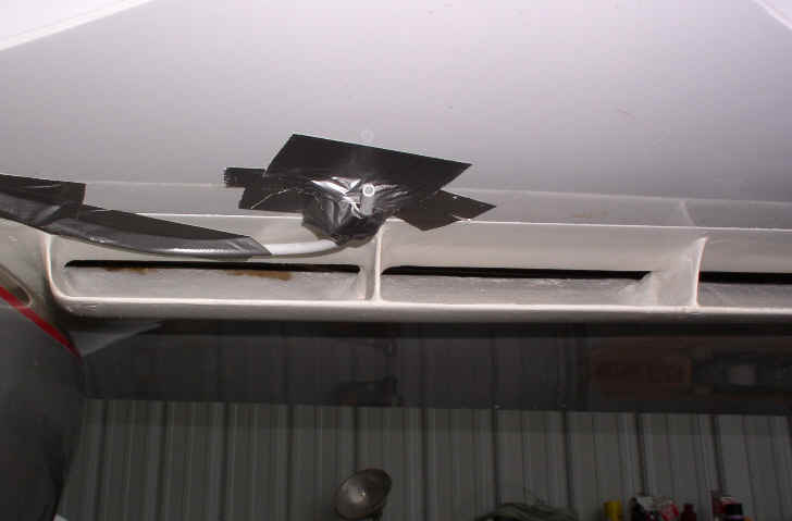
2 ? Installed Gurney flap at back edge of exit fairing (see photo 1) ? Very
little effect.
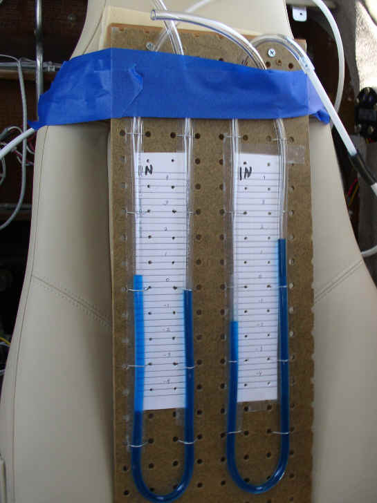
3 ? Set up manometer to get some pressures. (photo 2)
4 ? Dynamic pressure in front of scoop, ½? from surface (photo 3) -- 9.5? at
160 mph. Nothing wrong with that. Free stream away from surface would be a
bit over 12?.
5 ? Static pressure ½? from face of core ? 3 ¼? (end of tube was pointing
slightly away from direction of flow at about 60 degrees to the flow; flow
velocity is pretty low)
6 ? Static pressure just behind the core --- 0?
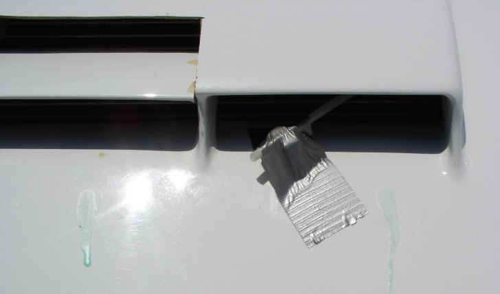
7 ? Static pressure at behind exit fairing, ¾? from surface (photo 4) ? ¾?
So .. . plenty of dynamic pressure in front of scoop and only 3 ¼? pressure
in front of the cooler core. This would suggest that the scoop/duct isn?t
working.
Photo 5 is a reasonably accurate x-section of the scoop and duct. Shaping
was limited because duct entrance is right behind the spar, and by the
limited thickness of the wing root. I'm just guessing that the somewhat
abrupt curvature of the upper wall at the entrance is causing flow
separation, turbulence; and whatever.
You'll also note in photo 4 that I had cut the center section of the exit
fairing to allow exit further forward - that didn't help. I also did soap
drops on the surface which way air was going both in front of; on top of;
and behind the fairing. In all places the flow was relatively straight
back. I'm also guessing that there isn't much chance of developing a
greater negative pressure at the exit; but, hey, whatever works
All I need to know is a simple fix:-)
Al
Well two things Al. You are measuring dynamic pressure with the front
hose. It is basically a pito tube but it says nothing about what
is going into the duct. The back hose is not exit pressure.
It is being affected by air currents passing over the open end
of the tube. If you want to measure static pressure you need
to hot glue porous foam on the end of the tubes. Ordinary kitchen
foam works fine. Also drip irrigation tubing is smaller than what
you have there and would cause less disturbance.
The front foam pressure tap needs to be inside the duct in contact with
the front face of the core. You should have four or five in there.
the rear foam pressure tap should also be in the exit duct in contact
with the aft face of the core. Again four or five.
IMHO your test set up is faulty.
I think your assessment of the duct shape is probably correct.
I can see no simple fix but good pressure data in four spots
on the front face of the core would help. You need more U tubes.
You could spend a lot of time getting the duct shape just right with
good data and still not get it to cool really well.
I know this is a challenge for you and you have some
creative individualism invested :)
If it were mine I would suck it up and take the core out of the
wing and place in in the cowl long ways and feed it with a Kays & London
wedge shaped diffuser connected to a P38 type ram air scoop.
Similar to what Perry Mick is doing. Last picture.
Paul Lamar ...No rotor no motor.
The Rotary Engine NewsLetter. Powered by Linux.
ACRE NL web site.
http://www.rotaryeng.net
Copyright 1998-2006 All world wide rights reserved.