Hey Al,
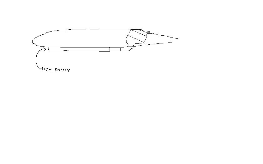
I think there's likely separation as illustrated in the first picture.
I think Paul is right about the wedge diffuser, but I don't think you
have
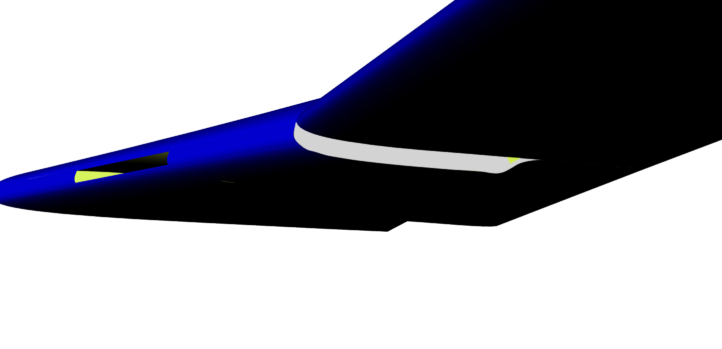
to move the cooler to the cowl. Maybe have a look at the 2nd pic...
What do you think?
Matt-
Al,
I vote for any form of scoop (ala P-51) that is moved far enough off the
surface to get out of the boundary layer. Ingesting boundary layer air is
never efficient regardless of how cosmetic it is. As an alternative, you
oversize the heck out of the cooler and get away with passing less air over
it.
Larry
No doubt that you are right about that. this configuration began the way it
did because another Velocity builder had put his standard aircraft oil
cooler (for a Lyc) in the same location, and said it worked great without a
scoop ? just the differential pressure above and below the wing was enough.
Go figure.
Actually in the location that it is, even an inch or less away from the
surface would make a big difference. Keep in mind that the scoop is about
23? wide with about 1 ¼? opening. How do you get BL diversion with that
configuration?
------------
Matt wrote:
How can we apply instrumentation in the duct so that we can tell where the
flow is becoming turbulent? Or we can just continue to guess... Since this
duct is not exactly like any in the books, we can't directly copy any
solution that's out there.. I believe Al's data is valid (it is what it
is), but a few more key data points could help make the picture clearer.
Hopefully we can talk Al into continue playing along.
-------------
I'll look at getting a bit more info.
Meanwhile; I'm looking toward the idea of a vane as what might be a
relatively easy fix. I think that my scoop opening is large enough, and the
BL thin enough, that if I can get effective diffusion in the duct it should
work just fine.
Note the attached diagram.
Al
A turning vane is worth a try. They usually don't work all that great as
they have form and skin friction drag even if they are not made out of sheet
metal
and are perfectly streamlined.
BTW that is an old diagram WW I era with an obsolete diffuser shape
guaranteed
to separate along the duct walls. Folks don't use that shape.
This plot from Hoerner sums up the situation fairly well.
Note again "w" is going to be a function of the actual airspeed flowing
through the
core. This can be measured with a pito tube pointing at the aft face of the
core.
----------------------------------------------------------------------------
This last plot deserves a bit of explanation since there is no factor
for boundary layer effects. Here they are.
What Hoerner is calling overflowing is now known as external diffusion.
It happens when the rad is not porous enough and can trigger the main flow
to flow around the opening and not in it.
Paul Lamar ...No rotor no motor.
From the pieces you've attached; I'm not getting the big picture, or the
message. Given that I'm working with a case which is in the BL; what I
glean from this is that a larger radius on the lip of the scoop could
improve the flow into the scoop. ??
Al
I don't think so. IMHO What happens is the pressure situation inside the
scoop is
also affecting the pressure at the entrance of the scoop. This combined with
the boundary layer thickness is enough to divert the high velocity air
stream
below the scoop opening.
These CFD's illustrate the problem.
You can use a blower to suck the boundary layer out from in front
of the scoop. If successful that will allow the high velocity air
stream to enter the scoop. Perhaps I'll have time to do another 3D which
will illustrate the trick.
You can also just shot gun it and put a two or three times larger opening
hopefully scooping everything up including the boundary layer.
Paul Lamar ...No rotor no motor.
Al,
Food for thought.... don't extend the scoop down. You could actually make it
shorter in height. Build an extension duct and move the entrance forward on
the wing. The closer you get to the leading edge, the thinner the boundary
layer, as a boundary layer gets thicker the farther aft you go on the
surface. In your case, you would have to have a part of the duct mounted on
the gear door and would loose it with the gear down. The pressure
differential created on the cooler this way would make the exit area non
critical. You could louver the exit for cosmetics and the cooler would still
function fine. This duct could start taller and narrow in the front and
gradually fan out to the width of the cooler while getting shorter, creating
a divergent duct in the process. A wide duct would require some internal
vertical supports to keep the bottom from ballooning, as it is a lot of
surface area even at low pressures.
Larry
Good idea Larry. I'll do a Rhino 3D. Something like a WW II Mosquito bomber.
Here they are.
Paul Lamar ...No rotor no motor.
The Rotary Engine NewsLetter. Powered by Linux.
ACRE NL web site.
http://www.rotaryeng.net
Copyright 1998-2006 All world wide rights reserved.