Al, could you summarize the various pressure measurements you have taken? A
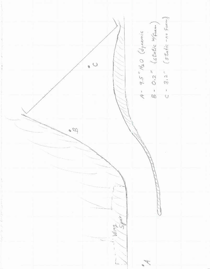
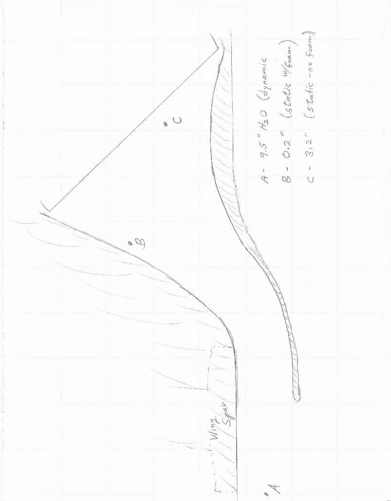
diagram of the cross section of the core and duct with symbols on it, each
symbol representing a different measurement location - sketch is fine. Then
a spreadsheet showing the measured pressure at each location and the
associated operating condition... Please indicate which measurements were
made with and without the foam on the pitot, and when without, what
orientation the tube had.
Thanks,
Matt-
-----------------------
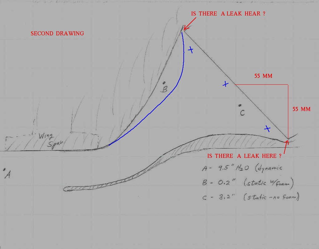
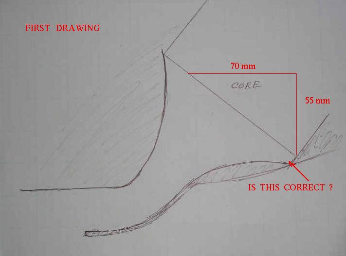
The attached sketch is a more accurate representation on the actual duct
shape (the previous one I posted was done from memory). It shows three
points that I measured related to the inlet. "A" was tube point directly
into the airstream (pitot style) about 4 - 5" ahead of the scoop; 1/2 - 5/8"
below the underwing surface. "B" was without foam tip, roughly perpendicular
to flow; "C" was with foam on the tip.
Three measurements were made at the exit; one 1/2" off the rear face of the
core perpendicular to flow, no foam - 0 pressure; one at the midpoint of the
fairing exit, roughly perpendicular to the flow, no foam -3/4" pressure;
one at the upper surface of the exit fairing, with foam, -3/4" pressure.
Al
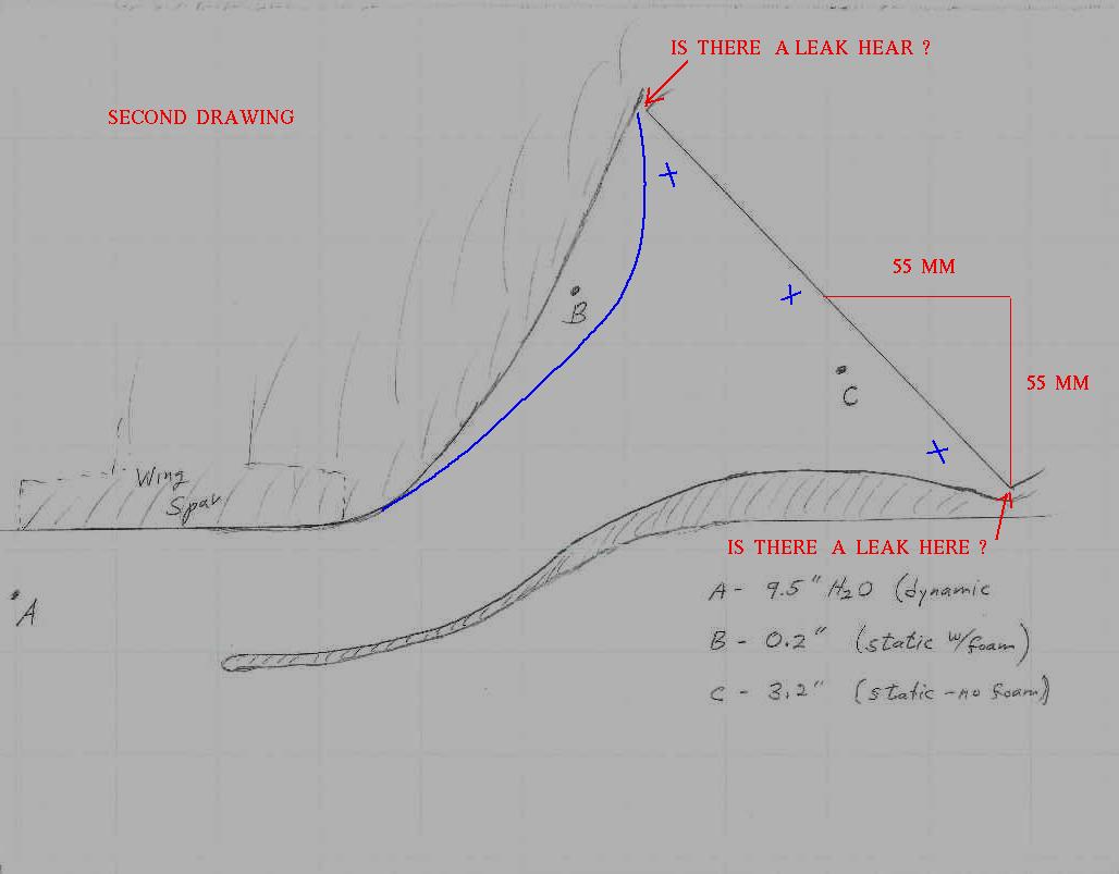
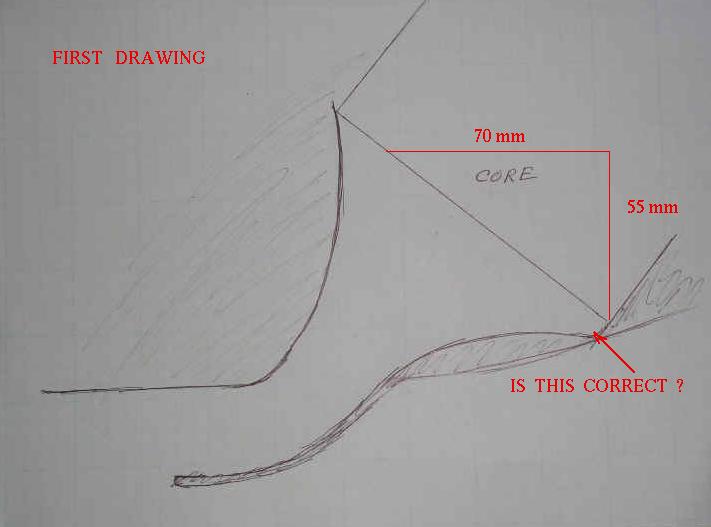
Now we are getting down to the nitty gritty. Are you sure there are no leaks
around the core? Before I can assess this I need a foam tap at point C. Also
foam taps at the blue X's taken simultaneously. One at a time does not cut it.
Too many variables.
Perhaps it can be improved with a new wall (blue line) but I need more data.
Paul Lamar ...No rotor no motor.
The Rotary Engine NewsLetter. Powered by Linux.
ACRE NL web site.
http://www.rotaryeng.net
Copyright 1998-2006 All world wide rights reserved.