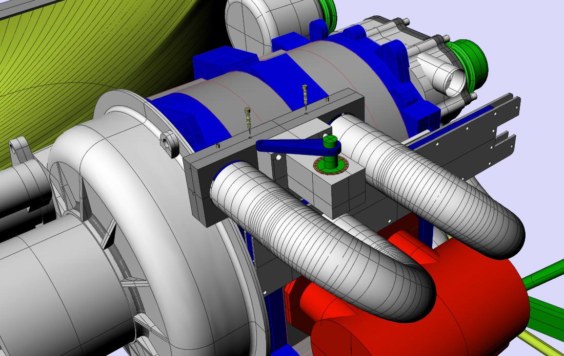
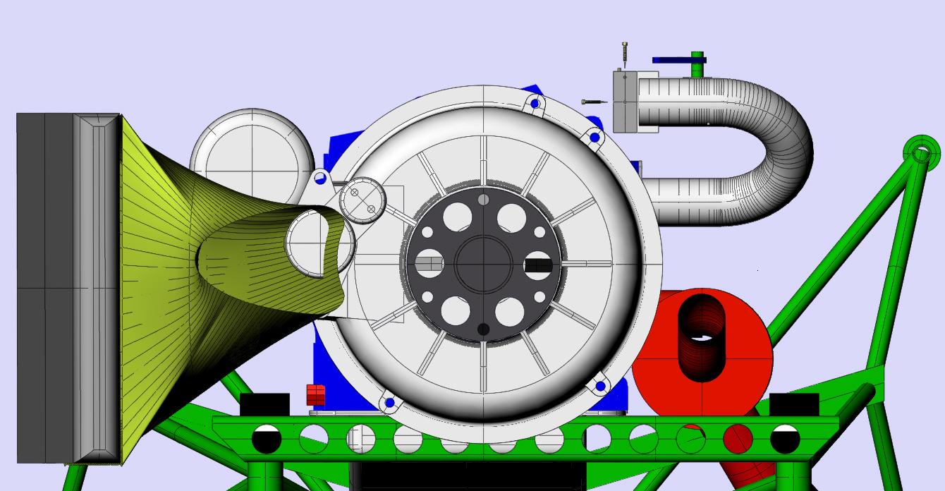
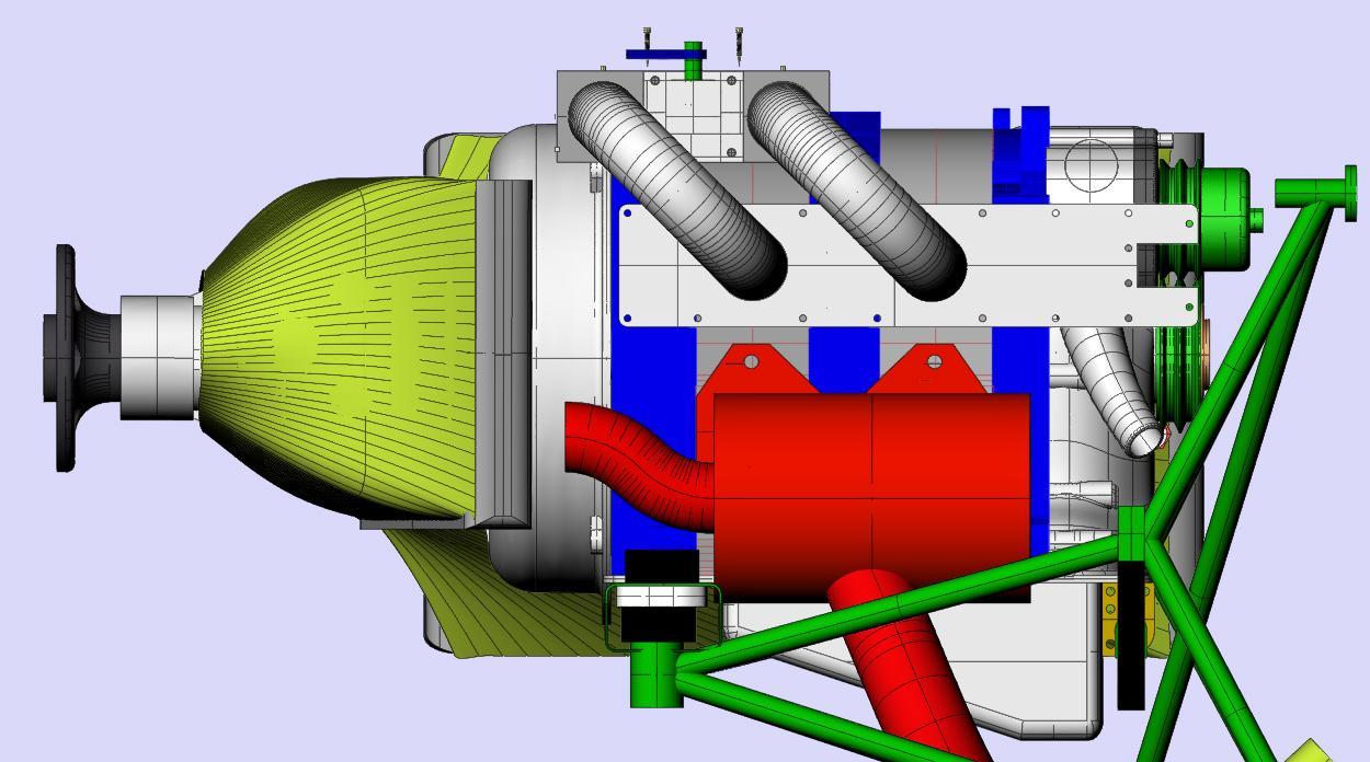
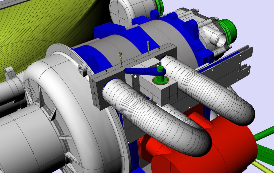
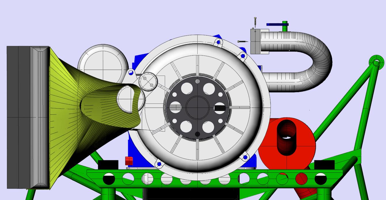
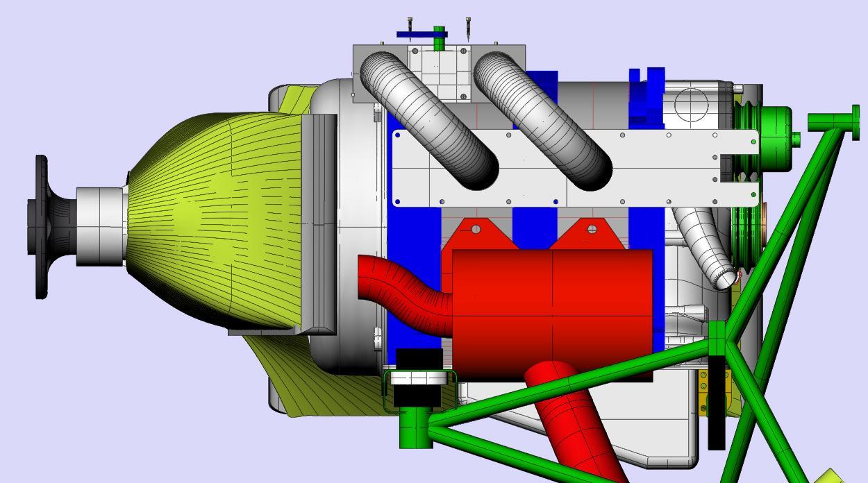
No longer a real carb. Mostly mechanical
fuel injections based on fuel pressure regulator design. Features:
1) One inch thick.
2) Two adjustable air injected fuel ports. One for each runner.
3) Two adjustable main jets.
4) Two bell or trumpet mouths. (Worth 5% more power.)
5) Built in pressure regulator. The pressure regulator is the
injection system.
6) Mounts on the end of the runners with simple clamps. (Detail not
shown.)
7) Fuel pressure port for mechanical gauge. (Not shown yet.)
8) Low technical risk. Based on the design of off the shelf regulators.
9) Fuel return line. (The only down side.)
10) Leaning over a wide range of mixtures by changing spring pressure.
The fuel mechanical pressure gauge will be mounted on the top of
the system to aid in tuning the engine. All one need do is
compare the gauge reading with the EGT or the wide band
O2 sensor. Also fuel pressure transients pulses due to rapid
throttle movement will show on the gauge allowing adjustments
of the MAP dampers and MAP controlled leaks in the back block.
----------------------------------------
Ops forgot the illustrations. Unless somebody comes up
with a major improvement this is the final design.
----------------------------------------------------
BTW turning the fuel pump off and moving the mixture knob
to full rich will seal the system and prevent fuel dribbles.
Paul Lamar ...No rotor no motor.
This will mount on the end of the inlet tubes? And still use a slide
throttle close to the housings?
Matt-
Absolutely Matt. That is central to the whole concept. We don't want to
bust what is out there already. The back block
can be flipped 180 degrees so the leaning lever comes out under the runners.
The lever can be flipped 180 degrees so the push pull leaning control cable
can work in a pilot familiar configuration.
Pressure taps are installed in the runners between the slide
and the engine. A pneumatic hose is connected to these taps. The hose is teed
together and fed into the back block of the FI. This has been proven to work
in Mark Suspinski's engine using Tracy's EFI system.
The runners can be rotated in side view to the right or left to
place this device closer to the engine and provide better cowl
clearance. Won't fit all airplanes but will help. Some airplanes
will require a bump on the cowl. It will clear most RV cowls no problem.
Another trick with those airplanes with wide cowls is to make
the lower sections of the runners longer and the upper sections
shorter. This will moving the FI off the top of the engine and
closer to the side of the cowl. This will allow lowering the
FI further.
------------------------------------------------------
Here is what I am trying to say. A 3D is worth a couple of
hundred words. This is an early slide throttle. The later ones
are shorter so there should be no interference with the new
bell housing. The limitation to this is the clearance
with the water pump inlets and outlets. Other combinations
are possible. Some stright runners sections top and
bottom may be better. The tilt angle on the runners
shown here is only 30 degrees. A tilt angle of up
to 45 degrees will lower the FI even further.
---------------------------------------------------
Even this one surprised me. Jerry Hey should love it as it
should fit under the cowl of a TailWind.
45 degrees forward.
Paul Lamar
The Rotary Engine NewsLetter. Powered by Linux.
ACRE NL web site.
http://www.rotaryeng.net
Copyright 1998-2006 All world wide rights reserved.