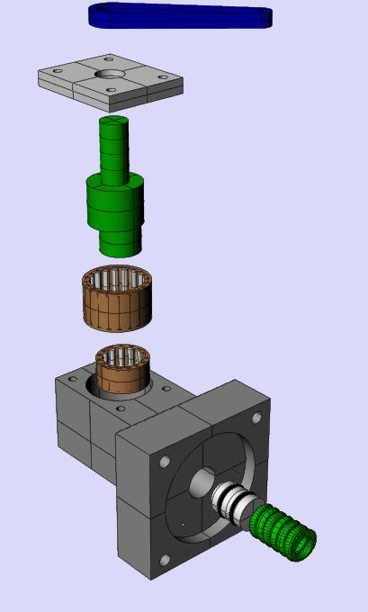
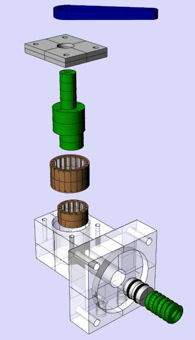
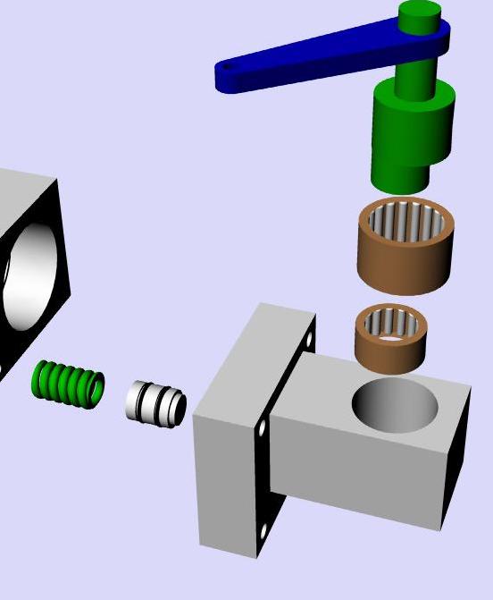
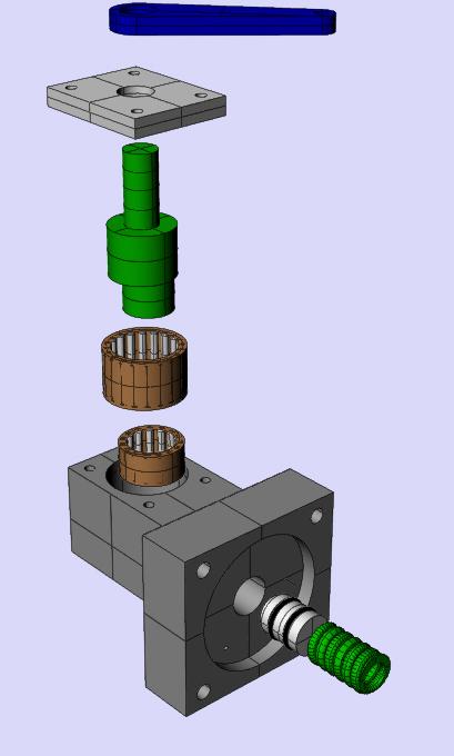
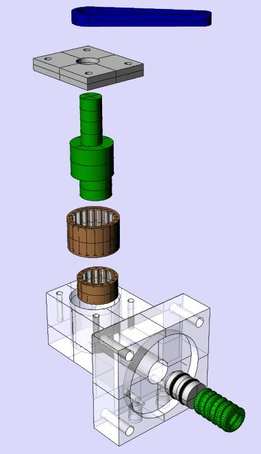
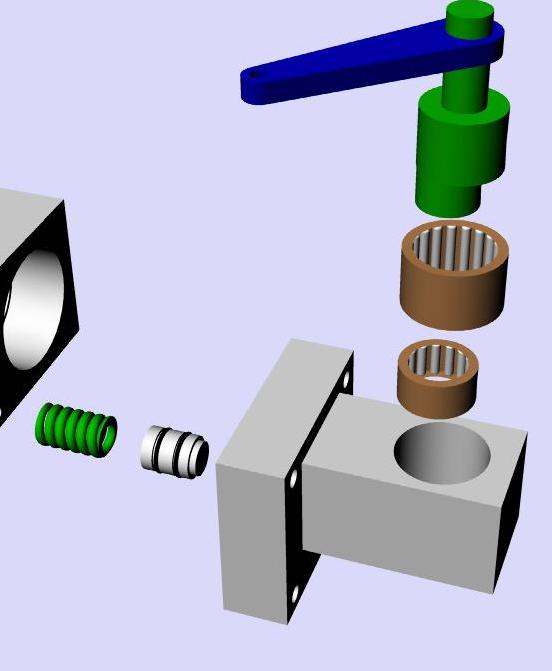
OK guys this is it. I used needle bearings because
I was worried about the friction load on the leaning
control cable.
Larry, no need to tap all the holes. I can do that by hand.
I tried to keep the tool changing down to a minimum.
The cover for the needle bearing bores has a counterbore
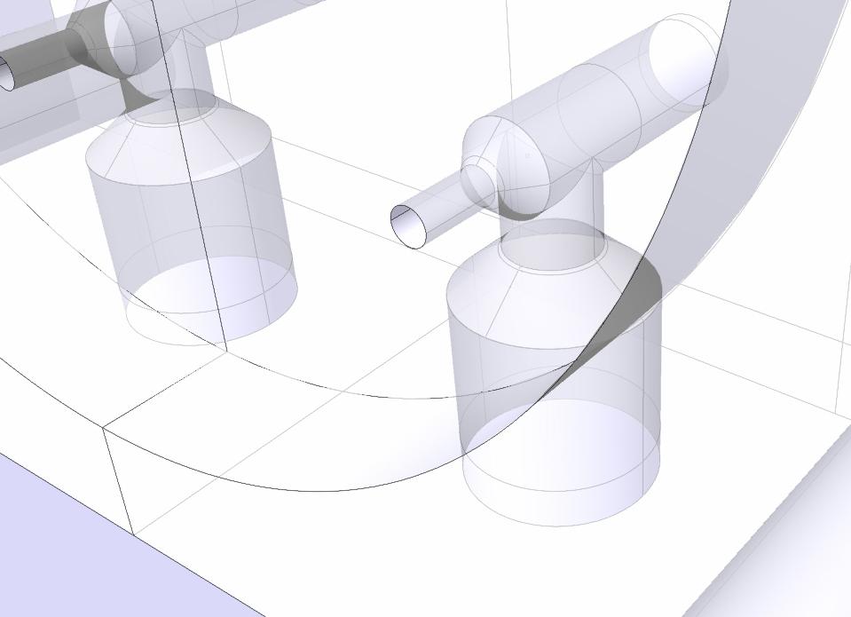
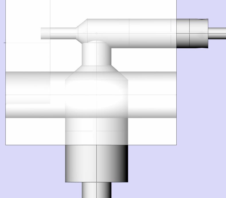
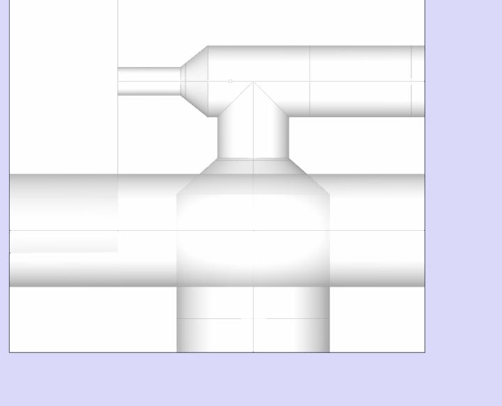
for a seal to keep the dirt out. The two ports under the back block
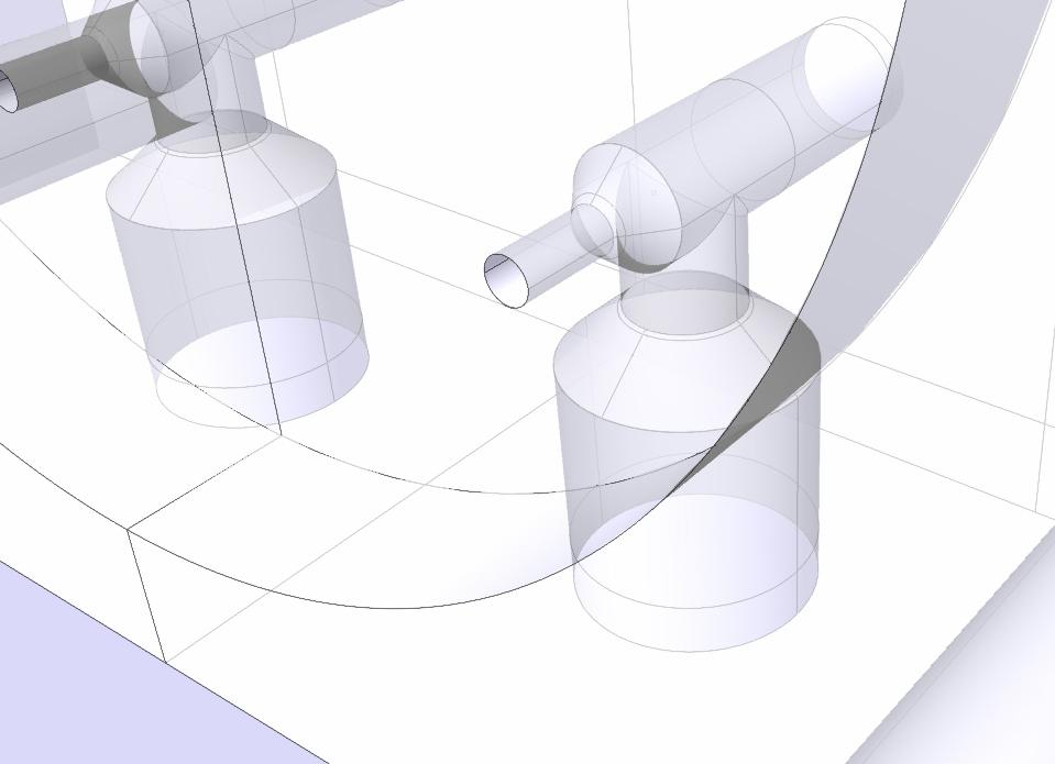
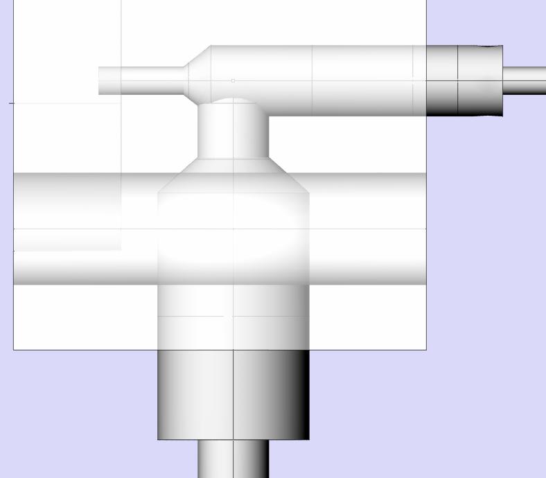
are for a couple of 10-32 needle valves. One is a damper on MAP
and the other is a MAP air bleed. Both will be taped for 1/8th NPT
pipe fittings. I can also make the spring spacer with the
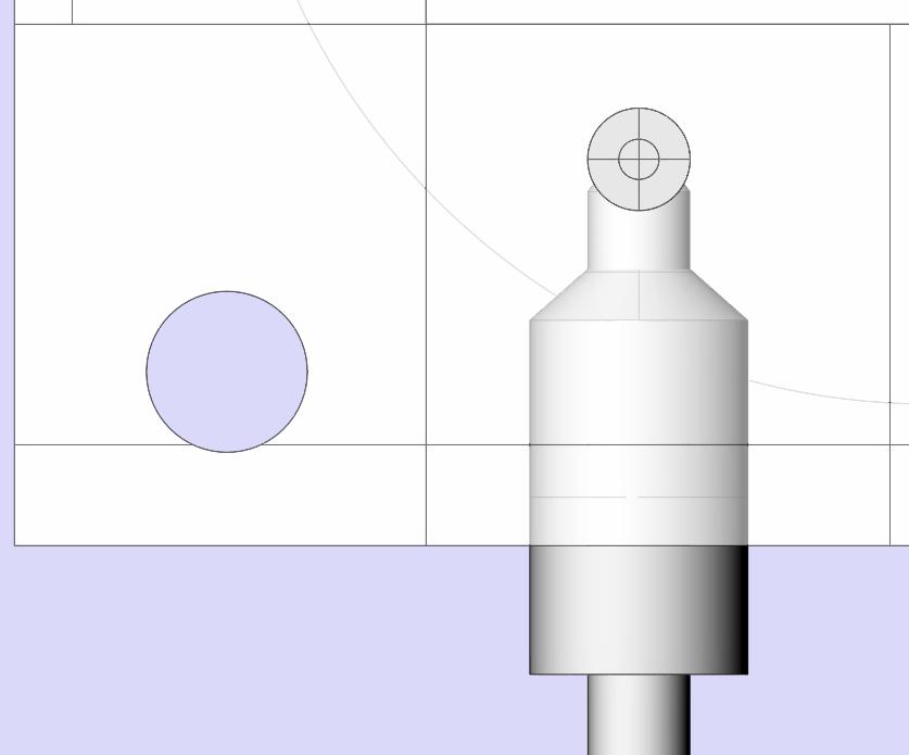
O-ring slots on my lathe. The steel eccentric shaft is beyond me
but it does not need to be hard or ground. Just a good finish.
The loads are not that high. Only about 60 pounds. Perhaps on
the production model.
There will be a 1/4 NPT port that I can
add on top for a small manifold pressure gauge. We will then have two
gages side by side. One for MAP and one for fuel pressure
so one will always have an over view of what this device
is doing. I can simulate operation on the bench with a hand
vacuum pump and a high pressure fuel pump. No moving parts
such as RPM input would require. I'll collect the fuel in two
burettes for exact calibration and rotor to rotor balance.
I think we can use inner tube tire rubber for the prototype
diaphragm. Total travel is only .2 inches.
The IGES will come by private email as it is too big to publish.
I am real excited about this product. Been thinking hard
and I see no reason why it won't work great. This should make
tuning easy and cut the cost of a 240 HP p-port slide throttle RX8
rotary engine installation by over $1,000. No EFI.
Paul Lamar ...No rotor no motor.
The Rotary Engine NewsLetter. Powered by Linux.
ACRE NL web site.
http://www.rotaryeng.net
Copyright 1998-2006 All world wide rights reserved.