Paul,
I am a 6000 hr helicopter pilot.
I am also a K-Max and Husky pilot, and have been on the Board of
Directors at Kaman Aerospace for 14 years.
The aero flap principle of the Kaman rotor-system is brilliant and
trouble free. I would heartily endorse its incorporation. What's
more, most of the original design team is still around for
consultation, if you would like to speak to the horse, as it were.
Just say the word.
-Reeves Callaway
On Aug 30, 2007, at 4:37 PM, Rotary Engine wrote:
This is stunning in it's simplicity.
since I am using the proven Ford A4OD six pinion planetary in a
differential
mode the total gear reduction is 6.34:1. The ring gear is rotating
in one direction and the planet carrier is rotating in the other.
As long as both props have the same drag the RPM's of each prop
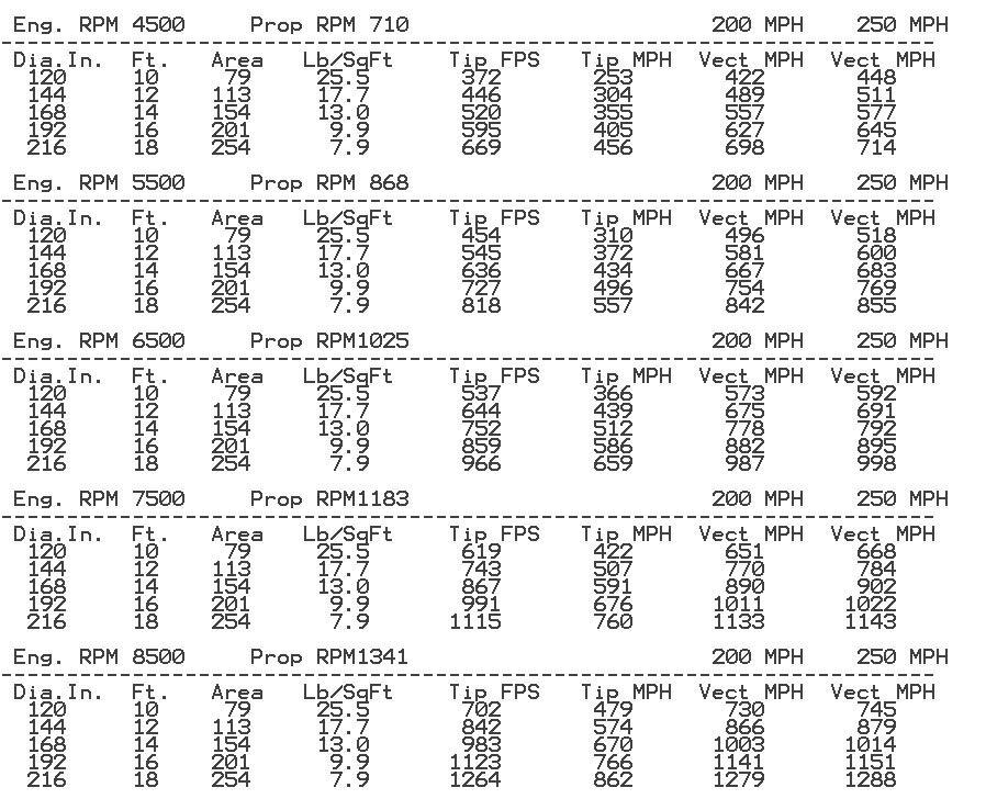
will be equal. With an engine RPM of 8500 the rotors will
be turning 1340 RPM. We can probably use a 13 to 14 foot diameter
rotor at this RPM. The red line on the RX8 engine is 9000
RPM and a P-port RX8 engine will be making close to 300 HP
or more at 8500 RPM. We will find out in a few weeks
as I am building such an engine as we speak
The over all diameter of this gear box is only
about 6.5 to 7 inches. It will have it's own oil
supply as it is on the very front of the airplane and
the engine is at the very rear for weight and balance reasons.
There is a stock RX8 carbon fiber drive shaft connecting the two.
The first 3D is with gear box housing.
The second is without gear box housing.
The third is with the aft prop shaft.
The gimbal is centered on the U joint which is a requirement.
The gimbal allows the props to be pointed in any direction with in
limits. The same as the Air Scooter. This will allow maneuvering in
landing
and take off mode and help with the transition to horizontal
flight and back to vertical flight.
Did we luck out or what?
Paul Lamar ...No rotor no motor.
Paul,
Interesting idea. In theory it should work, But on initial startup, both
rotors could turn the same direction. you will need to build a test
rig and
test the theory. Not being a forced synchronization, it may be yaw
unstable
in hover.
Larry
Yes that is true. I hadn't thought of that. Thanks for thinking of that
Larry.
Let me put my thinking cap on and see if I can come up with solutions
to these problems.
Once they are rotating the highest speed rotor tips will run into a
transonic
brick wall transferring the torque that is left to the slower rotor.
If we
make the rotors variable pitch the yaw forces in vertical mode can be
controlled changing the rotor blade pitch individually.
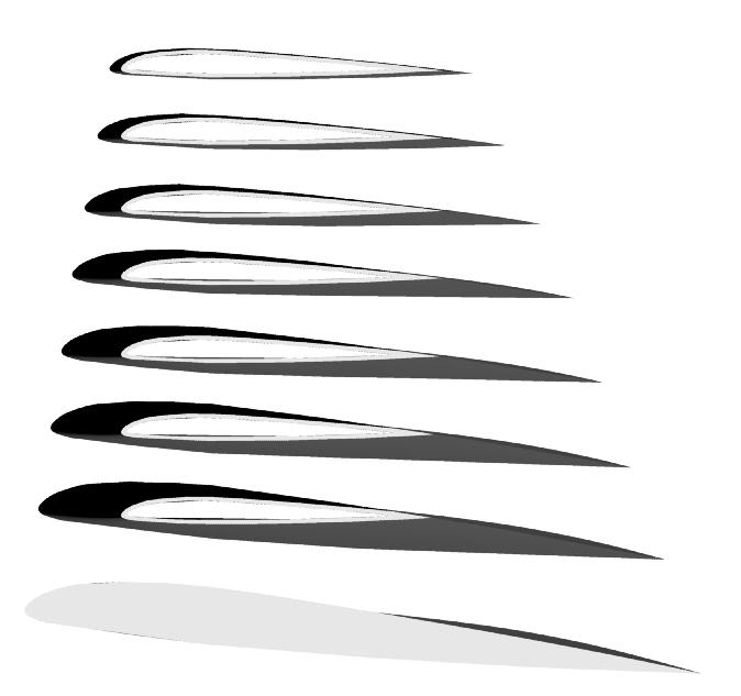
Here is a chart of drag coefficients of an airfoil as a function
of angle of attack as it approaches the speed of sound. Small changes
in pitch make large changes in tip drag.
Also one rotor can be feathered on start up to insure they rotate
in opposite directions. However one blade would be going backwards
so that might be sufficient torque load difference so the unit goes into
counter rotating mode.
BTW I am thinking of using an infra red or laser link and slip rings for
power to control the pitch on the front rotor electrically. Solves a
lot of
mechanical problems and saves a bunch of monkey motion pitch changing
parts. It could also be be done super imposing low level pulse width
modulation on the 12 volt power slip ring circuit. The power slip ring
would have to be located in the gear box working on the back side
of the planet carrier. This trick works on fuel pumps embed in
gasoline.
In that case
a stock high torque model airplane servo can be used to change
the pitch. The Kaman used an aerodynamic flap on the back of the
blade to change pitch.
http://www.b-domke.de/AviationImages/Rotorhead.html
"Kaman H-43 Huskie
Two-blade contra-rotating intermeshing twin-rotor with servo-flap
control.
Rotor blades are attached to hub by drag hinges only, the servo-flaps
eliminating blade pitch change and associated bearings. Movement
of servo-flaps twists the blades with the natural resilience
of the blades used to obtain torsional deflection."
I don't like twisting the blades because IMHO it does not lead to
the optimum pitch distribution along the length of the blade.
I could be wrong about this as helicopter blades are not very
torsional stiff to begin with and they may have a mind of their
own when it comes to local pitch. Kaman may be on to something
in this regard. Kaman's do have a reputation of generating a lot of
lift however so some of that could be due to no tail rotor
sucking engine power.
I would rather use a torsionally stiff carbon fiber blade
rotating around a bearing in the hub. The aerodynamic servo flap
can still be used to control pitch.
Since we will not be flying forward in helicopter mode for long the
leading and lagging hinges can be done away with. Same goes
for the flapping hinges. I think we can use GRP for the
hub. Same as several European helicopters use. GRP has high
tensile strength and a low modulus of elasticity allowing it
to flex without failing. Same as the Long EZ main landing gear.
Paul Lamar ...No rotor no motor.
This is correct that the servo tab on the Huskie (and the K-Max)
twist the
blade and the lift distribution is not what you might like. I think
they
cheat a bit with the twist of the blade so that when the aircraft is
hovering at gross weight, the entire blade is at optimum angle. The
Seasprite has a very stiff blade while the portion of the spar that
connects
the blade to the rotor head has a much lower modulus so it does the
twisting, not the blade. That's why I want to get a close look at one.
That Eurocopter has one of the best rotor heads available.
Steve Brazil
Thanks for the insight on that Steve.
--------------------------------------------------
Redesigned the rotor head as we no longer need cyclical pitch change.
We will be using the vectored thrust trick of the Air Scooter.
I changed it to simple mechanical pitch change. I increased the size
of the aft
shaft to the same size as the ring gear. Namely five inches. A
simple butt weld
is all we need. One of the results of this is the gear case now
becomes a simple
piece of thick wall aluminum tubing about six inches in diameter and
eight or
ten inches long. This also allowed increasing the diameter of the
front shaft
connected to the planet carrier to four inches. The front shaft needs
a lot of
torsional and bending stiffness as it is cantilevered a fair distance
out of the gear box.
I will probably use plain bearings, oil filter and an oil cooler with a
dedicated high
pressure stock Mazda 13B oil pump driven off the input shaft. The
remaining problem would be high speed shaft seals.
Next will be telescopic rotor blades to increase the speed range of the
VTOL canard from zero to about 200 MPH.... to zero to 300 MPH.
Might as well take full advantage of all that 300 HP.
Paul Lamar ...No rotor no motor.
Paul,
I am a 6000 hr helicopter pilot.
I am also a K-Max and Husky pilot, and have been on the Board of
Directors at Kaman Aerospace for 14 years.
The aero flap principle of the Kaman rotor-system is brilliant and
trouble free. I would heartily endorse its incorporation. What's
more, most of the original design team is still around for
consultation, if you would like to speak to the horse, as it were.
Just say the word.
-Reeves Callaway
Wow! I didn't know that. Please send them some of this stuff and have
them tell me what they think. I am sure they can come up with
some serious advice and improvements.
My goal here is to go faster than the Osprey which can go about
275 MPH. I think 300 MPH is within our grasp if this telescopic blade
can be made to work. It will be molded in a closed mold preloaded
with carbon fiber. One end of the mold will be subject to a vacuum and
the other end will have epoxy resin injected at high pressure.
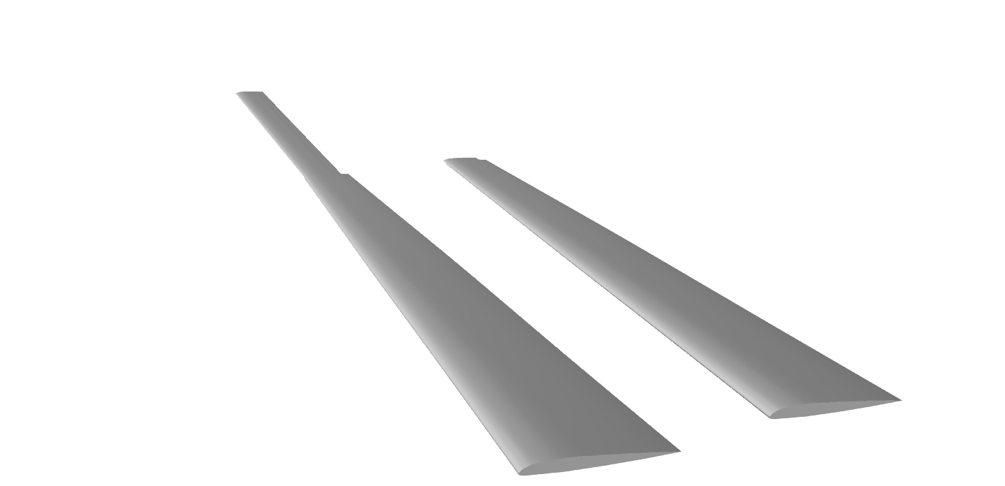
There will be a left and right acme screw passing through the short
part of the blade from end to end. One side will be a left hand thread
and the other side will be a right hand thread. There will be an
coaxial electric motor in the hub that turns the screw. The acme nuts
will be located on the inner ends of the outer blade segments.
The inner blades will have a slight twist so the untwisted outer
portions can be retracted. Not ideal blade twist but it is a better compromise
than trying to run a large diameter rotor at high RPM in forward
flight due to Mach limitations on the tip speeds.
This scheme is designed to double the blade diameter for vertical takeoff.
Paul Lamar ...No rotor no motor.
The Rotary Engine NewsLetter. Powered by Linux.
ACRE NL web site.
http://www.rotaryeng.net
Copyright 1998-2006 All world wide rights reserved.