I am getting a Lenco catalog on the way.
Lenco has a 91 tooth ring gear and a 23 tooth sun gear for
an over all ratio of 3.95:1. Counter rotating the blade
ratio is 7.98 for each blade. That allows us to use a larger
rotor diameter and still keep the tips to .8 mach or
so at 300 MPH. The diameter of the 91 tooth ring
gear is about 8 inches so it is a bit larger and heavier than the Ford
set which is around 5 inches OD. That makes it pretty bullet prof
so we
may not need the Lenco one inch wide set. The 3/4 set might be fine.
In any event here is the new tip speed chart so we can go up about a
foot
on the rotor diameter without using the telescopic blade idea.
This configuration holds the most promise for solving the general
aviation
dilemma.
http://www.rotaryeng.net/VTOL.html
Paul Lamar ...No rotor no motor.
I made a mistake. I am disappointed in you guys for not catching
this :)
There was a bug in my tip speed calculation program. It over
estimated tip speeds.
The stock Ford 3.17 planetary is fine the way it is. We don't need
no stinking
Lenco gears :) Much cheaper. The last jpg is the corrected chart.
I'll have to
fix the web site.
This is looking better and better all the time. We can use a 13 foot
diameter
rotor for a disk loading of less than a Robinson or up the gross weight
a couple of hundred pounds. We could smoke everybody off in the
Dayton to OSH race.
They would not know what hit them. We don't need no stinking Reno.
Next problem is lay out the cooling and fuel tanks. I am going to
engine
fan cool it during take off and disconnect the fan for forward flight.
We need to set up a corporation to develop this. Do we have any CEO
types on here?
Paul Lamar ...No rotor no motor.
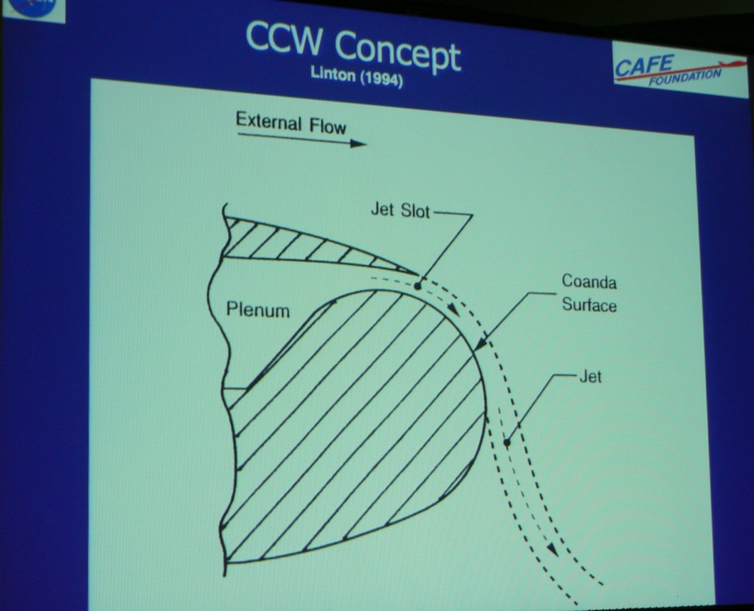
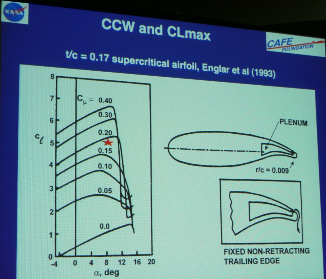
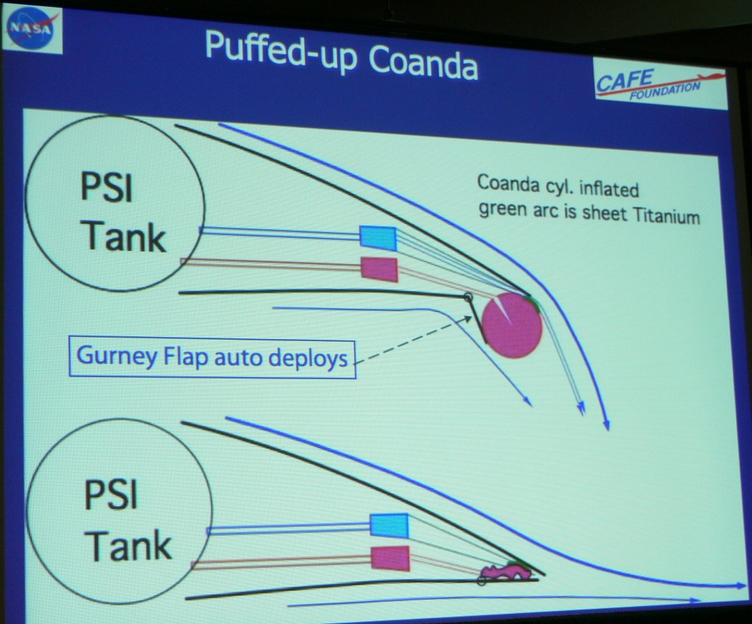
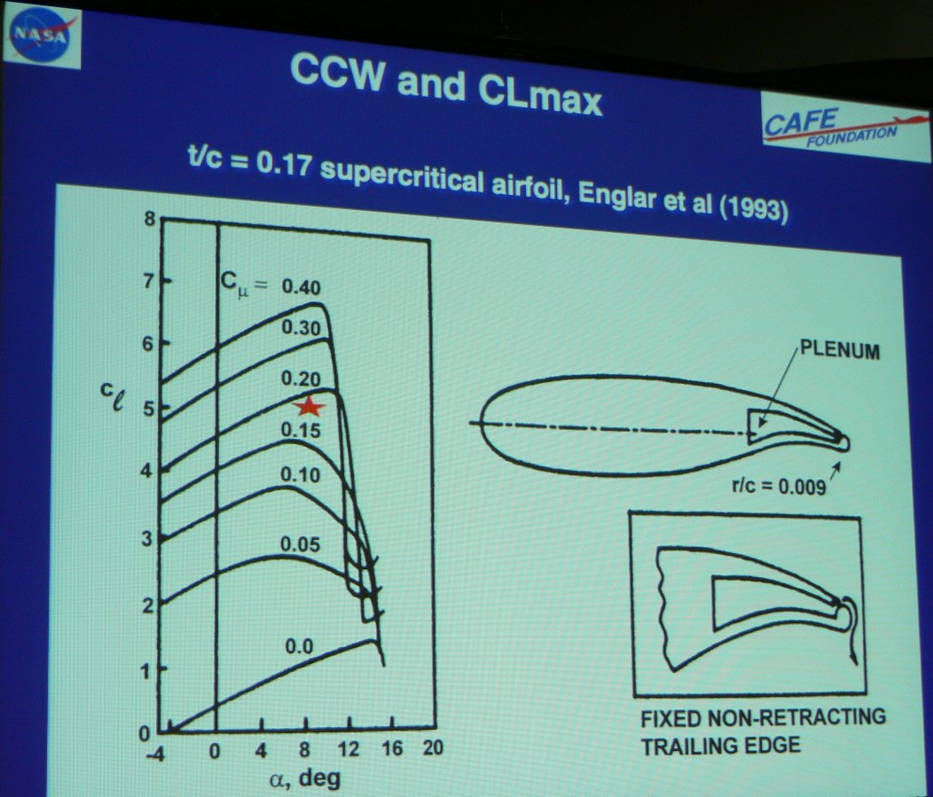
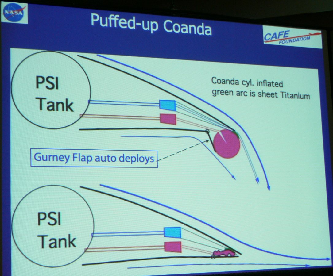
Interesting Paul.. However, I've been noodling around with another idea
which in some ways competes with a VTOL effort. As we have discussed
here in the past, the rotary seems to have exhaust energy to spare -
even well above that required to run a turbocharger. How about using
all that excess exhaust energy as a means to provide boundary layer
control for the wings? With boundary layer control, much lower speeds
are possible for a given wing loading (increasing the lift
coefficient?). I know this has been done on turbine airplanes -
applying a vacuum to the top of the wing. Also, the C-17 Globemaster
apparently uses a "blown" wing, which I think is the other side of the
same coin. With a short enough takeoff roll you can compete with most
helicopter applications. A plane that can takeoff in 100ft, and cruise
at 200kts would be impressive enough for me.
On the rotary, run the exhaust to a large turbocharger. Maybe the input
to the compressor coming from the boundary layer control system, and the
output of the compressor to the engine inlet - providing boosted
manifold pressure. I haven't run any calcs on required pressures or
volumes...
I am not a fan of extra whirling things if I can avoid them.
Regards,
Matt-
That would help but it would only reduce the length of the runway. Tilt rotor
STOL is zero length and it works now. No need for R&D. The R&D has been done
over the past 50 years.
People have implemented schemes like that in the past with mediocre results.
I don't know if they used exhaust. Brien Seely was advocating that at
the SAE meeting but he was using a high pressure storage tank and an
air compressor.
Anyway other than Alaska most runways are at least 2500 feet. No need.
With a better power to gross weight ratio, fowler flaps, slats and a larger diameter,
slower turning prop you can get off in a lot less distance. 470 feet over
a 50 foot obstacle for the Helio. I think the Helio Courier
used the GO-xxx. Some had the IO-720. No R&D on that either.
http://www.stolaircraft.com/h295specs.html
--
Paul Lamar ...No rotor no motor.
The Rotary Engine NewsLetter. Powered by Linux.
ACRE NL web site.
http://www.rotaryeng.net
Copyright 1998-2006 All world wide rights reserved.