--
Paul Lamar ...No rotor no motor.
I think it would start shaking pretty good as soon as you started getting
some translational lift. Did you look at that website I sent?
http://www.rotor-international.net/
It uses co-axial two-blade rotors and they appear to be underslung with
short beams that twist for feathering, flex for coning and may be servo-tab
controlled. Look at how far apart the rotors are. I think if you want the
flexure to to accomplish lead and lag, the flexible portion should be
outside the feathering bearings. The stiffer the system is, the more moment
applied to the hub and the more vibration.
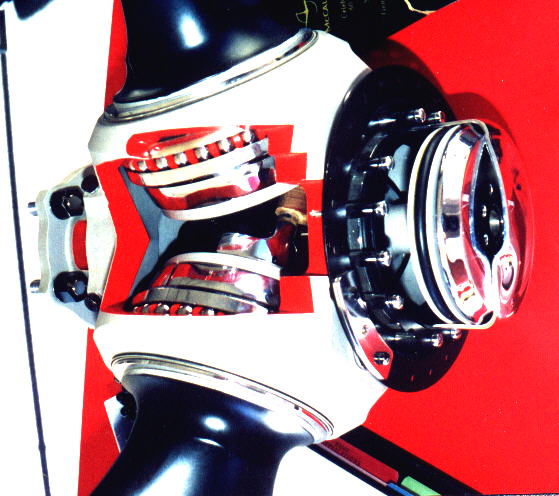
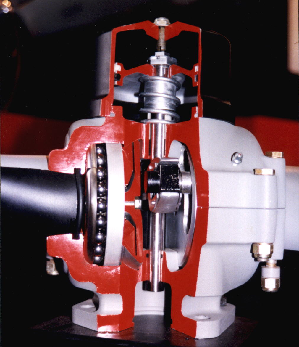
I think on the model you've shown, with one bearing race, when a moment is
applied to the assembly the loads on the bearings could get pretty high. A
second bearing race inboard would help, especially if it were an angular
contact type that could take high thrust loads and it was located far enough
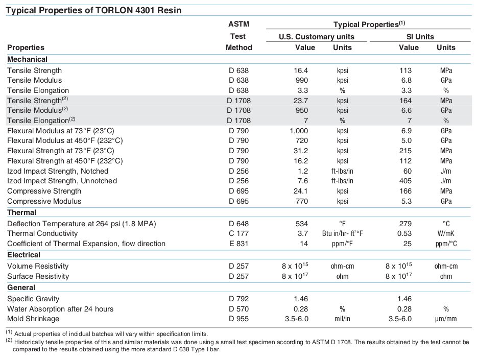
inboard to resist to the applied moment. I'm not sure about those Torlon
bearings being strong enough, but with two races, they might be and you
would avoid the shear load that would occur with your model and the loads
would be all compressive. The slight elasticity of the Torlon may help
distribute the load which would be a good thing as well.
Steve
I don't think so. We don't do much translational lift. It is an arcing takeoff with
considerable vertical velocity for only a second or two.
I looked at that web site but I saw no details of the hubs. If you see something
there in detail please do a screen capture and email that.
All constant speed props are built with only one bearing. The negative bending
moment on the blade hinge due to centripetal force acting on the blade CG counteracts
the positive bending moment due to thrust. Therefore it only needs one bearing.
If the constant cord blade weighs 20 pounds
and it moves up one foot at it's CG radius position that is a negative bending moment
of 100,000 foot pounds. The centripetal force on the 20 pound blade is 100,000 pounds.
Weight/32.2 x FPS^2. The positive bending moment due to thrust on the blade is only
6.5 ft x 300 pounds (each of four blades will need to generate 300 pounds to lift the
1200 pound craft.) or about 2000 foot pounds.
Obviously the rotor blade CG is not going to move up one foot. The upwards
deflection of the blade at its CG position will only be about .2 feet or 2.4 inches
balancing the thrust moment. That puts a negligible bending load on the bearing compared
to the centripetal load. All props and rotors work this way. If not rotors and blades
would break off at the hub because they do not have the bending strength on their own
to support the weight of the helicopter.
The bearing consists of 22 half inch dia. balls. In effect they act like 22 1/2 inch
dia. bolts in single shear. The centripetal load is 100,000 pounds so each half inch
bolt only needs to accept 4,500 pounds of shear roughly. A 1/2 inch bolt has an area
of about .2 square inches. So the shear stress on the bolt will be 22,500 psi
roughly. A piece of cake for a steel ball but maybe marginal for a Torlon
ball. Consequently I will try to get the carbon fiber blade weight well below
20 pounds each.
As you can see the centripetal force is orders of magnitude higher than the
bending loads on the blade hub. It is all about numbers.
Paul Lamar ...No rotor no motor.
The Rotary Engine NewsLetter. Powered by Linux.
ACRE NL web site.
http://www.rotaryeng.net
Copyright 1998-2006 All world wide rights reserved.