Paul
I noticed many intake designs have constant diameter intake pipes while
Guru Racing and a few others taper theirs down to the intake port.
I will make my intake manifold out of carbon or some other heat
resistant
glass epoxy GRP so I am free at the moment as to the course and
profile they
will be.
I thought to go from 60mm id at the intake plenum with the adjustable
length
portion being able to extend another 120mm within the intake intake
plenum.
From the plenum to the slide throttle, a distance of about 320mm I
would
like to taper the tubes down to 50mm gradually over their length.
Injectors are right after the slide throttle so fuel mist separation
is not
an issue. Other than being a pain in the butt to construct the
tapered pipe
are their any disadvantages or advantages to such a design?
Thanks
Doug
It is mentioned in:
Scientific Design of Exhaust and Intake Systems. Philip H. Smith
and John C. Morrison Published by Robert Bentley. ISBN 0-8376-0309-9
http://www.rb.com
--
Paul Lamar ...No rotor no motor.
Doug,
Concerning information given to me on inlet manifolds.
My understanding is that any reduction (such as a Venturi) in an inlet
is a
restriction. However if a small restriction increases velocity without
choking the flow, it has an advantage for VE.
Alternatively any increase in size (especially toward the engine end) the
flow will slow and will be a disadvantage.
I'm advised that THE OPTIMUM SHAPE is a megaphone shape starting
larger at
the outmost end and ending at the port, in a even taper. The air flow
starts
out larger than the port, builds pressure and speed, but like you
said, the
hard part is building the darn thing!.
Probably the same reason why those tapered exhausts work so well in 2
strokes .
George ( down under)
Do you have any mathematical theory to support this contention or is
it an
opinion? If it is an opinion do you have (or the person that expressed
their opinion
to you) have any empirical data to support their contention.
Paul Lamar ...No rotor no motor.
Hi Guys;
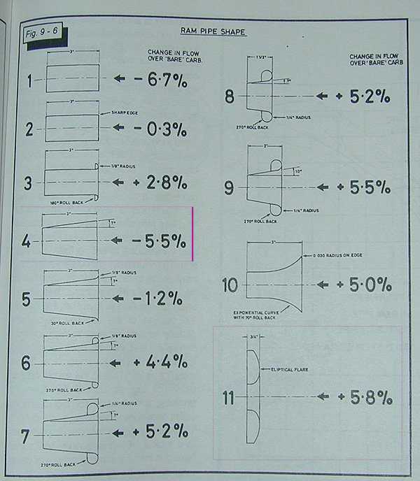
Attached is a pic a local fellow sent some time ago detailing a
comparison of various intakes.
I would love to know the source - unfortunately he could not find it...
I'm guessing the front top surface of any laminar flow airfoil revolved
into a body of revolution like a bellmouth
would be beneficial in terms of drag reduction by delaying the
transition point from laminar to turbulent (then separation)
with favourable pressure gradients. 2D airfoil software (such as xfoil)
shows this. 3d multi-element
or CFD results would be nice :)
I have heard of performance increase claims in the 15-25% range -and
many rules of thumb for tapered gradients.
Check out something like the following for claims of big results:
http://www.bpinitiatives.com/products.html
There is no question you can reduce drag but the big question is how
much turbulence results in optimal power
and at what range of intake velocities? as is being done with some of
the latest turbulent flow intakes?
Fuel routing is greatly simplified if all the injectors are in a closely
spaced row nearer the housings.
I vote for the adjustable length intake for maximum flexibility with
varying ambient conditions and just in case our exact
calculations and reverse engineering don't match reality :)
Cheers
Cary
That is really interesting Cary. Thanks for the data. We knew the bell mouth was
worth about 5%.
--
Paul Lamar ...No rotor no motor.
The Rotary Engine NewsLetter. Powered by Linux.
ACRE NL web site.
http://www.rotaryeng.net
Copyright 1998-2006 All world wide rights reserved.