Paul
I noticed many intake designs have constant diameter intake pipes while
Guru Racing and a few others taper theirs down to the intake port.
I will make my intake manifold out of carbon or some other heat
resistant
glass epoxy GRP so I am free at the moment as to the course and
profile they
will be.
I thought to go from 60mm id at the intake plenum with the adjustable
length
portion being able to extend another 120mm within the intake intake
plenum.
From the plenum to the slide throttle, a distance of about 320mm I
would
like to taper the tubes down to 50mm gradually over their length.
Injectors are right after the slide throttle so fuel mist separation
is not
an issue. Other than being a pain in the butt to construct the
tapered pipe
are their any disadvantages or advantages to such a design?
Thanks
Doug
It is mentioned in:
Scientific Design of Exhaust and Intake Systems. Philip H. Smith
and John C. Morrison Published by Robert Bentley. ISBN 0-8376-0309-9
http://www.rb.com
--
Paul Lamar ...No rotor no motor.
Paul
I sense this has been an well debated subject on your newsletter:) I did
find a forum that gave me a clue to stay with constant diameter pipes and
verify length on the dyno. My concern has always been what happens
when the
supercharger or turbocharger fails. Assuming I have a bypass valve I am
suddenly operating in a N/A mode so that would need the testing.
........................................
http://www.physicsforums.com/showthread.php?t=80364
"You will need access to an engine dyno to determine the optimal runner
length/shape and optimal plenum shape. Intakes and exhaust systems are
voodoo black magic throw the chicken bones pieces of an engine and
need to
be designed as such. You could do Helmholtz
http://www.phys.unsw.edu.au/~jw/Helmholtz.html calculations to match the
runner length to your desired operating band but in the end without a
dyno
to test various runner lengths you're just shooting in the dark at a
target
even the automakers can't theoretically hit. Yes, even the automakers use
dyno's to determine the optimal designs for their intakes.
Now you can get close (Ricardo
http://www.mscsoftware.com.au/produc...sy5_engine.htm ) to help you
predict
a good design but require reams of data to be even 20% close to an
optimal
design.
For a force-fed application, runner design is less of a factor than for a
N/A design. Plenum volume is the key---the rule of thumb is plenum
volume >=
engine volume when force-fed. A large plenum has a few draw backs
though so
it is not the magic bullet either. A large plenum breathing through a
single
butterfly will have a lag between throttle opening and engine response.
Basically, there is no easy recipe for intake design. There are some
rules
of thumb---long thin runners=low end torque, short fat runners=high RPM
power plenum volume=engine volume for supercharged applications but
there is
no perfect solution nor is there an easy formula (Helmholtz
calculations can
get pretty scary when one takes valve timing exhaust pulse velocities,
intake pulse velocities exhaust length and desired operating
conditions into
consideration---even then there are 12937492137 not even accounted
[factors]
so you are nowhere near optimal)."
No chicken bones bones at our house I wonder if mouse bones will work?
Doug Fir
Paul & Doug,
On the theory that getting a good impedance match for the acoustic wave
between the plenum and the engine intake throat will give the best
performance, I think the Guru tapered designs are on the right
track. An exponential horn would work. But, at the 100hz to 125hz
acoustic frequencies involved, there would be no way (here comes the
proverbial aircraft trade off) to fit a proper exponential horn into an
airplane. And, I'm not sure how you could have both a horn and variable
length. But, here is the horn I like the most for attempting an
impedance match on a fixed length intake. It is the Quadratic Throat
waveguide developed by Charles Hughes at Peavey Electronics. It
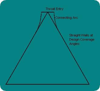
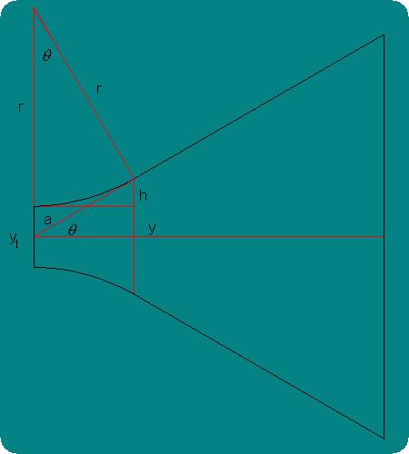
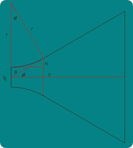
combines a straight sided (megaphone style) mouth with a circular arc
taper on the throat. The geometry is shown in the attachments and would
be easy to reproduce with a composite structure. I would let the
mouth(s) be the whole side of an air filter box. Then, the remainder of
the geometry is defined by the throat size and how much length you can
fit in. Hughes' study can be found here:
http://home.carolina.rr.com/charliehughes/Articles/QTWaveguide/QTWaveguide.html
Hughes found that the acoustic wavefront remains spherical in this
horn. So, the interaction between horn mouths at the plenum should be
predictable. Of course our acoustic wave is superimposed on a moving
stream. One big unknown is how this matters.
Aubrey Thompson
The Rotary Engine NewsLetter. Powered by Linux.
ACRE NL web site.
http://www.rotaryeng.net
Copyright 1998-2006 All world wide rights reserved.