> >> Paul
> >>
> >> I noticed many intake designs have constant diameter intake
> pipes while
> >> Guru Racing and a few others taper theirs down to the intake port.
> >>
> >> I will make my intake manifold out of carbon or some other heat
> >> resistant
> >> glass epoxy GRP so I am free at the moment as to the course and
> >> profile they
> >> will be.
> >>
> >> I thought to go from 60mm id at the intake plenum with the
> adjustable
> >> length
> >> portion being able to extend another 120mm within the intake
> intake
> >> plenum.
> >> From the plenum to the slide throttle, a distance of about 320mm I
> >> would
> >> like to taper the tubes down to 50mm gradually over their length.
> >>
> >> Injectors are right after the slide throttle so fuel mist
> separation
> >> is not
> >> an issue. Other than being a pain in the butt to construct the
> >> tapered pipe
> >> are their any disadvantages or advantages to such a design?
> >>
> >>
> >> Thanks
> >>
> >> Doug
> >>
> >> It is mentioned in:
> >> Scientific Design of Exhaust and Intake Systems. Philip H. Smith
> >> and John C. Morrison Published by Robert Bentley. ISBN
> 0-8376-0309-9
> >>
> >>
http://www.rb.com
> >>
> >>
> >> --
> >> Paul Lamar ...No rotor no motor.
> >
> > Doug,
> > Concerning information given to me on inlet manifolds.
> > My understanding is that any reduction (such as a Venturi) in an
> inlet
> > is a
> > restriction. However if a small restriction increases velocity
> without
> > choking the flow, it has an advantage for VE.
> > Alternatively any increase in size (especially toward the engine
> end) the
> > flow will slow and will be a disadvantage.
> >
> > I'm advised that THE OPTIMUM SHAPE is a megaphone shape starting
> > larger at
> > the outmost end and ending at the port, in a even taper. The air
> flow
> > starts
> > out larger than the port, builds pressure and speed, but like you
> > said, the
> > hard part is building the darn thing!.
> >
> > Probably the same reason why those tapered exhausts work so
well in
> 2
> > strokes .
> > George ( down under)
> >
> >
> > Do you have any mathematical theory to support this contention or
> is
> > it an
> > opinion? If it is an opinion do you have (or the person that
> expressed
> > their opinion
> > to you) have any empirical data to support their contention.
> >
> >
> > Paul Lamar ...No rotor no motor.
>
> Hi Guys;
> Attached is a pic a local fellow sent some time ago detailing a
> comparison of various intakes.
> I would love to know the source - unfortunately he could not find
> it...
> I'm guessing the front top surface of any laminar flow airfoil
> revolved
> into a body of revolution like a bellmouth
> would be beneficial in terms of drag reduction by delaying the
> transition point from laminar to turbulent (then separation)
> with favorable pressure gradients. 2D airfoil software (such as
> xfoil)
> shows this. 3d multi-element or CFD results would be nice :)
>
> I have heard of performance increase claims in the 15-25% range -and
> many rules of thumb for tapered gradients.
> Check out something like the following for claims of big results:
>
http://www.bpinitiatives.com/products.html
> There is no question you can reduce drag but the big question is how
> much turbulence results in optimal power
> and at what range of intake velocities? as is being done with some of
> the latest turbulent flow intakes?
>
> Fuel routing is greatly simplified if all the injectors are in a
> closely
> spaced row nearer the housings.
> I vote for the adjustable length intake for maximum flexibility with
> varying ambient conditions and just in case our exact
> calculations and reverse engineering don't match reality :)
> Cheers
> Cary
>
> That is really interesting Cary. Thanks for the data. We knew the
> bell mouth was
> worth about 5%.
> --
> Paul Lamar ...No rotor no motor.
>
>
> The real effect that a "bellmouth" has is to act like an effectively
> longer pipe. It doesnt really "make for faster flow" because the
vacumn
> signal at the source, i.e. port, is a function of VE. The "bellmouth"
> allows for a more rapid transition to laminar flow in a shorter
distance
> which is the same as having a longer pipe allowing for the Re
number to
> drop until is it turns into fully developed flow. You can get the
same
> results but having a long pipe but this is limited due to space and
> acoustics.
>
> The other more important thing is the acoustics more so that
> anything. You need to tune your lengths based on wave theory
(helmholtz,
> impedence modelling) since acoustics will actually spit fuel air back
> out if you are not careful. Go look at the video on youtube.com
of the
> Renault F1 v10 running on the dyno and you will see the vapor getting
> spit right back out of the "bellmouths" due to acoustics forming an
> almost inpenetrable layer. Just simply adding a bellmouth to
something
> may end up hurting you if you are starting to fall off of ou tuning
> peak. It would be real interesting to see someone run the numbers
on a
> rotary running at the 6000rpm you guys are always talking about.
I have
> a SAE paper that shows how to calc impedence methods and a simple
way of
> doing a realworld test with microphones and a manifold.
>
>
> Rob Woods.
>
>
>
> You need to read the web site Rob:
http://www.rotaryeng.net/intake.html
>
> The spit back is common to all tuned manifolds I have seen.
>
> That is one reason why I designed this air box for this car.
> If you have a picture of an earlier race car with this feature please
> send it to me. I think it was a first.
>
> Paul Lamar
Rob,
I don't know if I can agree with all your statements, however I
agree with
harmonics are at play, as you mention.
To my knowledge a sharp edge will cause turbulence entering the manifold
tube, to eliminate this the rounded edge is used. This provides smoother
flow into the tube - the further the rounded edge is as it returns
back to
the outer tube wall the smoother the air will access the inlet tube
without
turbulence. The better entrances will have at least 180 degree rounded
edge - the more the better in my opinion.
As mentioned previously a tapered inlet (megaphone type) is the better
option and I notice is Cary's document this is proven to be the case.
My personal option is that the primary advantage is better entrance flow
minizing turbulence and restriction.
George (down under)
Hey George,
This stuff is basic fluid mechanics/dynamics. Entrance conditions either
lengthen or shorten the length it takes to get fully developed flow. It
is possible to be a restriction but the head loss portion of fluid calcs
are usually rather small but still worth talking about. I am just saying
that entrance conditions really don't impede the volume flow rate that
can get to the engine. I was just stating before that there is a fine
balance between these entrance conditions and loss vs the required
runner length. I mean a fine balance between fully developed
flow(ideal), and acoustics length tuning and the actual physical
makeup.
If your intake is long enough and that is what wave theory wants
then you dont even have to bother. At Delphi we use a 55 gallon drum(to
make it acoustically dead), a 3 foot long pipe with no radius' and a
calibrated MAF in order to do VE tables for chassis and engine dynos.
Its all in what the calcs tell you that you need. I see people throwing
radius horns on stuff because they saw it on a Can Am car 30 years ago
when what is below it is a complete mess of turns, weld beads,etc.
This paper should be small enough to send over. It is a really good
paper on theory and experimentation.
Rob Woods
Thanks for the paper Rob. Interesting As far as I can tell from a
quick perusal
it does not address the skin friction drag of the runners. A
function of both the diameter
and the length of the runner. Obviously that is a factor. Here is
some data from Heinz
Heislers book Advanced Engine Technology. Unfortunately it is not a
complete data set.
Paul Lamar
Paul,
Any standard fluid mechanics/dynamics book will have charts for days on
all sorts of surfaces and finishes. If your fluid inertia is high enough
then separation on a smooth surface wont have that much effect. Turns in
the tubing have more effect than surface finish. Again here is the
balance. In p-port setups it always seems the fuel is injected furthur
back than it should. You want a certain amount of roughness to keep the
fuel from pooling but not so much that you get those losses. Also
injecting that fuel before the turn just throws it against the wall and
puddles up. (Guru manifolds?) Sure you know all of that already. I have
done labs to verify the theoretical results and they are really close. I
really like the microphone test rig they made up. Very powerful tool and
so easy to test out. I have some real good papers on turbos and choking
flow to get really big numbers. Lemme know if you want it. Big file though.
Rob Woods.
Yes I have the Granger book on Fluid Mechanics.
Well as you can see from that chart the diameter of the runner has a strong
effect on the frequency and the VE. Something IS going on in there.
Here is a chart from Taylor on piston engine intake manifold mach numbers.
What clouds the issue with piston engines is you have a fixed area around
the intake valve and usually the valve lift is held constant. Therefore changing
the diameter of the runner may have less of an effect. With a P-port there
is no intake valve and the area and diameter of the port is the same as the
runner area and diameter. Enlarge the runner and you enlarge the port.
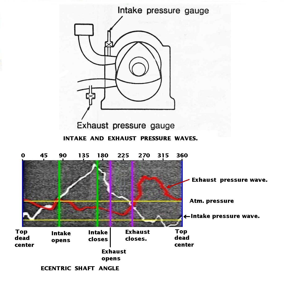
Here is a pressure graph adapted from a Mazda paper on P-ports. I just cleaned it
up and added the e-shaft angle.
Finally notice as the RPM and power is increasing the VE is going down
on the Lemans engine. What I would like to see is a complete data set with
a range of runner diameters along with this range of runner lengths.
With four runner diameters and five runner lengths that would be twenty
curves as a function of RPM.
I think the the fuel pooling concept is left over from carb days. With individual
injectors any fuel that pools will either get sucked in or it will sit there
and never get any bigger or smaller. It will not have a long term effect on the
amount of fuel going into the port the runner is connected to. In our case
gravity will see too it the fuel runs down and into the port. The reason
the fuel is injected at the beginning of the runners is it results in a better
BSFC on dyno tests. In effect it is no different than mounting a two barrel
carb on the end of the runners. We have done that too on the dyno. Several times.
The engine shown is now in Mark Supinski's Mustang II airplane. It starts right up and
runs fine although as far as I know Mark has not tried to tune it with a prop load yet.
Paul Lamar ...No rotor no motor.
The Rotary Engine NewsLetter. Powered by Linux.
ACRE NL web site.
http://www.rotaryeng.net
Copyright 1998-2006 All world wide rights reserved.