I don't know why I did not think of this a couple of years ago.
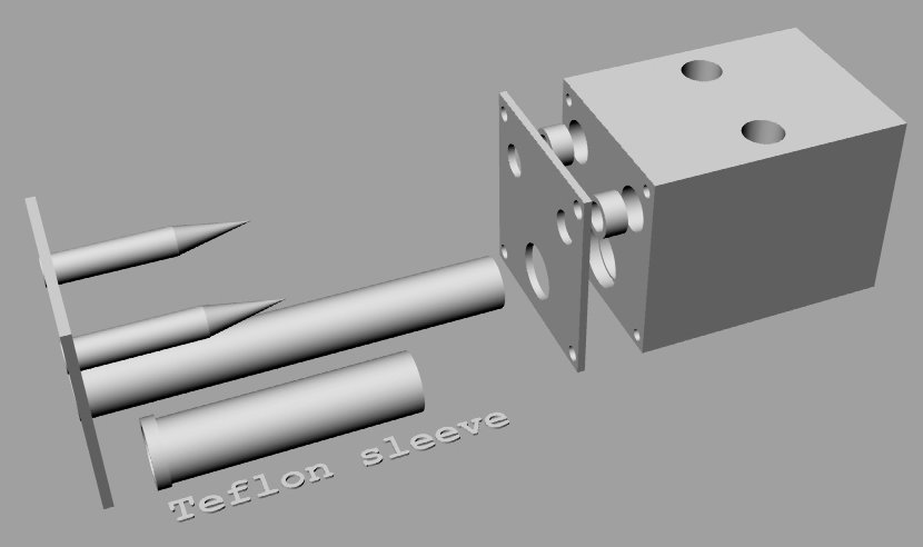
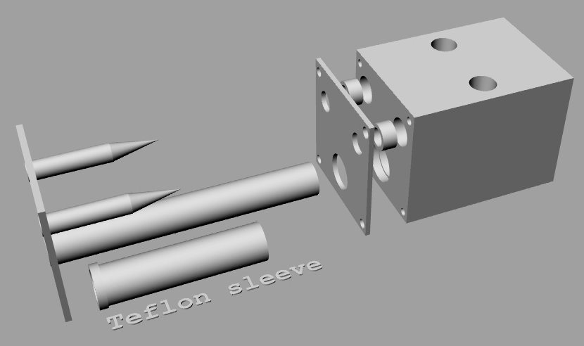
I just was not thinking fixed needle movable fuel jet.
This is by a factor of ten simpler and easier to build than
anything I
have come up with
so far. It uses a low pressure pump and a low pressure pressure
regulator.
Your done!!!! Assuming you have a slide throttle. Adjust the
regulator
to
lean.
Turn the pump on after the engine is turning over to start.
To prime turn the pump on for a second or two and then off.
Paul Lamar ...No rotor no motor.
Paul,
This seems to be a fixed needle, (with integral needle and jet) x 2.
Wouldn't the fuel therefore need to be fed to the other, thicker
end of
the
needle.The biggest draw-back of a fixed needle is getting the
fuel to the
jet, as the jet would be in most cases moving with the slide.
You have designed around this problem but I do see a couple of
things to
consider, like the thickness of the needle- rod , but that is just a
relative thing ( i.e. fuel flow to air flow). I would personally
go for
the
flat ground needle to maintain more width thickness of the needle,
therefore
keeping the needle diameter down to the smallest size.
One of the claimed draw-backs of the round ground needle is that
it tends
to
rub against the jet wall in one area and causes uneven wear of
the jet,
that
leads to an uneven flow distribution. However where it's one
piece like
this, there isn't that sort of problem.
I may be wrong but I thought that round ground needles needed the
increased
signal of a venturi to better draw the fuel. That's why I like
the flat
ground needle as it creates it's own low pressure area behind
the needle,
which draws the fuel up through the jet. Then again you
mentioned the low
pressure pump and Regulator to initiate and maintain correct
fuel flow. I
will use the same system but just enough pressure to get the fuel to
within
striking distance, to respond to the low pressure area created
by the
flat
ground needle.
If I am seen to be pushing the flat ground needle, it's just
because I
would
like both yourself and Doug to fully understand the benefits,
before you
eliminated it as a contended for a design.
One other thing to consider is fuel cut-off, but I suppose you
will just
cut-off the fuel pump?
George (down under)
Here is the needle design and a chart showing fuel jet port area
as a
function
of the smaller diameter of the needle. The OD of the needle is
.2 inches.
Looks like the small diameter should be about .16" for a fuel flow
of 22 gallons an hour high power at 2 psi fuel pressure.
This is going to be one super cheap FI system using only off the
shelf
low
pressure fuel pumps and an adjustable low pressure regulator.
Dave, hang on to my RX8 p-port engine. I am making one of these
and we
will be trying it again on the dyno soon. Stand off mist should
not be a problem as the fuel is injected down near the engine
16 inches away from the runner bell mouths and about 3 inches
in from the p-port itself. In other words inside the sealed slide
throttle.
--
Paul Lamar ...No rotor no motor.
Paul,
Most adjustable low pressure fuel regulators go to 6 psi, so if your
set-up
shows your running too lean you can adjust your regulator. I see the
regulator as the course adjustment and would suggest a fine
adjustment of
the needle, simply by having a thread and nut to adjust the
needle up and
down (back and forth).
Of course most needles aren't just one linear line form fully open to
fully
closed, they are stepped and change from idle to cruise to wot.
Exactly
where and by how much is a matter for experimentation. This is
where an O2
sensor comes in handy, as it will identify where the needle is
too thick
or
too thin.
George ( down under)
That is a REAL good idea George. Really easy to implement on this
design
as the needle sticks out the front end of the slide. Thanks for
thinking
of
that. It could be motorized even with a big gear and a small
pinion turned
by a DC motor.
I don't think you need the stepped needle because in an aircraft
engine
you adjust the leaning at steady RPM cruise. You take off at WOT.
It is
not
like a car or a motor cycle where the RPM and load vary over a
wide range.
All you need is to keep the engine running and the rotary will
run from
about
10:1 to 18:1 mixture.
--
Paul Lamar ...No rotor no motor.
Paul,
You may well be right about the needle taper, I hope you are, it
would sure
make things easier.
On the threaded adjustment of the needle, this could be manually
done, as it
is currently done - from the cockpit / turn knob, for rich and lean,
with
the cable going from cockpit ( knob) to the needle/jet threaded rod.
This is how I plan my rich/ lean adjustment also.
The next thing I would reconsider is moving away from the electric
pump and
going back to the manual pump you designed a little while back OR
have both
for redundancy. Certainly use the electric pump for testing.
The carb discussion has been very stimulating, I wish Doug had
tossed in his
2 cents worth. It's always interesting to see others opinions and if
I have
contributed in any way - it's my pleaser to do so. Acceptance of an idea
reinforces that I am heading in the right direction also.
George (down under)
I kind of like the idea of an engine driven primary pump. I haven't
been keeping up with the details of this injection/carb system (I
apologize), but an engine driven pump might make flow regulation
easier. As the engine slows down the pump can supply lower
pressure/volume. Then you just need to regulate fuel flow based on
manifold pressure (or mass flow).
Use the electric pump to prime and as a backup.
Regards,
Matt-
Paul,
Engine driven pumps aren't linear to pressure/flow needs of the engine at
each particular rpm, so they have to be oversized and have a bypass valve
within the system. The system could be similar to Mazda's common fuel rail
with the unused flow returning to the tank.
To adjust flow we have to adjust the pressure, the orifice size or perhaps
both. The adjustable orifice valve however doesn't need to be built into the
slide. Without depending on a venturi for metering fuel I would think you
would want it separate in any case. I can't imagine how you can get an
efficient shape that way in any case though I understand your wanting to
simplify the mechanical connections by combining it. The problem is the
slide has a throw of about 2", and adjustment of needle valves in the range
of liquid flows we are interested in, happens in less than a 1/16" linear
travel, hence the need for several revolutions of the knob to fine adjust
them. These valves are efficient in regulating flow because of the small
amount of side wall restriction, read short needle length, and large volume
of liquid in the valve body cavity. The profile of the conical shape seat
initially creates a donut shaped spray. As the needle is fully withdrawned
out of the flow, up into the cavity, there is a conical spray of the maximum
orifice chosen.
For an electrical pump system you have an interesting idea with the PWM
pump. In such a case we could use a pressure sensor instead of a pressure
regulator and modulate the pump according to the pressure (and hence flow)
we desire. Fuel flow would still have to be mapped based on air inlet temp,
air flow, and perhaps by MAP or a mass and throttle position sensor. To
richen or lean it we could fool the pressure sensor.
This still begs the question as to where to inject the fuel. Why not right
behind the throttle like the Lemans had it? For a quick dyno test can't you
just install several appropriately sized off the shelf needle valves into
the intake manifold downstream of the slide throttle, run your fuel lines to
them and manually tweak them? Start with them fully opened and adjust fuel
flow of an electric pump with a simple PWM circuit. Bench test your flows
and settings before going to engine testing of course. Start rich and slowly
manually lean them down.
There is another easier way to do it of course. One that has years of proven
research behind it and millions of engines and race experience. Install
electric fuel injectors and let them be PWM:)
Doug in Japan
"The problem is the slide has a throw of about 2", and adjustment of needle
valves in the range of liquid flows we are interested in, happens in less
than a 1/16" linear travel, hence the need for several revolutions of the
knob to fine adjust them."
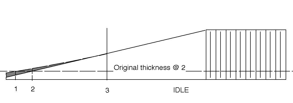
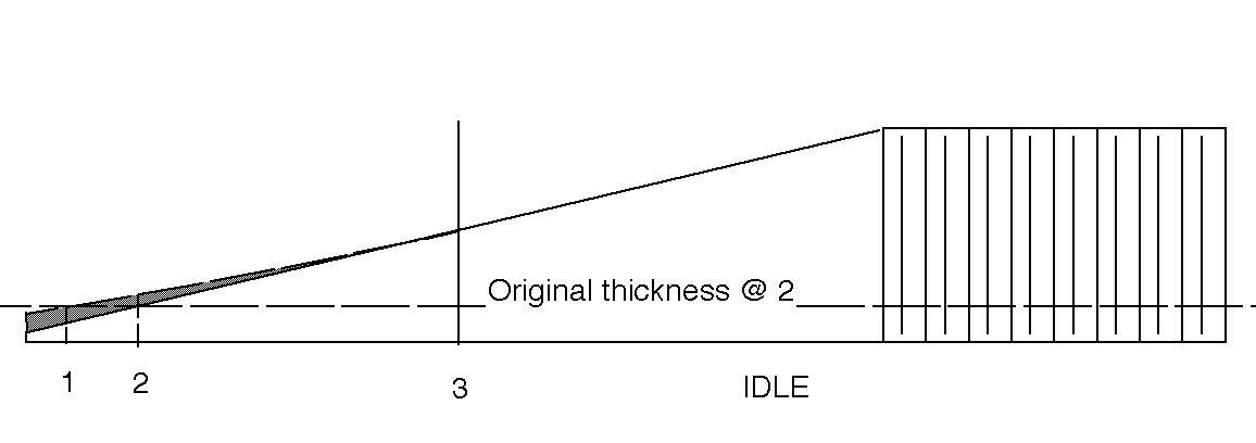
You are talking about a very short needle here. Apples and oranges. A long needle
works in a carb BECAUSE it is long. Two inch long needles are ad-van-tages and
not a drawback. The longer the better. Here is a needle curve out of a Posa
carburetor. The diameter of the needle can be adjusted along its length.
There are half a dozen brands of long needle carbs that work fine.
Unfortunately PWM is NOT working too well in aircraft. Besides the
extra expense, users have trouble installing, tuning and maintaining the
PWM EFI system. Most people are not electronic technicians let alone EE's. It is
way overkill for the average aircraft engine. Manually tuned aircraft
carbs also have years of proven research and use behind them too :)
We need something Joe Sixpack can understand and fix :) Present
company excepted :)
What works in a piston engine may not work in a p-port rotary. See my
last message.
Paul Lamar
The Rotary Engine NewsLetter. Powered by Linux.
ACRE NL web site.
http://www.rotaryeng.net
Copyright 1998-2007 All world wide rights reserved.