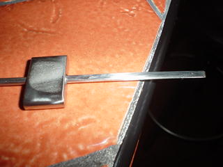
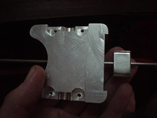
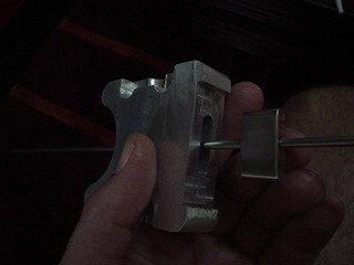
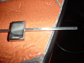
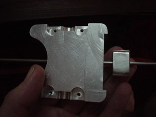
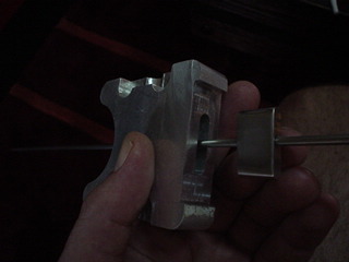
It is coming right along. We found a center less grinding
outfit 10 miles from Santa Paula in the small town
of Fillmore Ca that has agreed to do a range of fuel needles
for us. Very convenient. The precision of this
needle is crucial. One thousands of an inch difference
of diameter can result in a change of fuel/air mixture.
The grinding outfit can hold 1/10 of a thou accuracy.
We will have a range of needles that we can change
during the dyno test until we find one that gives a
reasonable mixture across the RPM and load range.
If anybody wants to build one of these my friend
Jim Poole can machine the hard part for you. Fortunately he
has a right angle milling head for his Bridgeport mill
as that is what it takes to drill the long needle hole in the
slide. There is not enough vertical travel in the mill head
and foot.
--
Paul Lamar ...No rotor no motor.
Paul,
Looking good, however I can't understand why you need a number of needles
when only one would do if you adjust it with a threaded end - especially
since your taper is totally linier. It seems an overly complex way of doing
it to me.
I have my needle seated on a spring and a threaded rod that pushes on the
needle guide. The spring keeps the needle and guide positively positioned
against the threaded rod - which also acts as the throttle.
Turning the rod pushes the needle and guide up and down, leaning and
enrichening - pushing and pulling on the rod is the throttle control. With
one knob you can throttle and lean, at the same time if you want to.
Attached is a photo of the needle in guide (slide carb 13). The spring
slides over the needle and sits under the guide, the needle and guide slide
into the slide plate (slide carb 18). Again in 19. There is a top plate with
a threaded centre hole which the throttle rod screws into and pushes on the
needle and guide.
Can't get much simpler than this!
George (down under)
The Rotary Engine NewsLetter. Powered by Linux.
ACRE NL web site.
http://www.rotaryeng.net
Copyright 1998-2007 All world wide rights reserved.