It is pretty easy to devise a new ignition system.
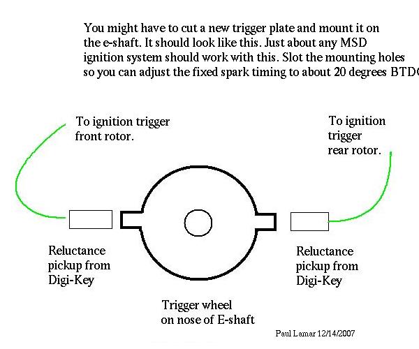
You might have to cut a new trigger plate and mount it on
the e-shaft. It should look like this. Just about any MSD
ignition system should work with this. Slot the mounting holes
so you can adjust the fixed spark timing to about 20 degrees BTDC.
The trigger plate can be cut out of 1/4 inch thick mild steel
with a computer controlled plasma or laser cutter.
...
Paul Lamar ...No rotor no motor.
<trigger-wheel.jpg>
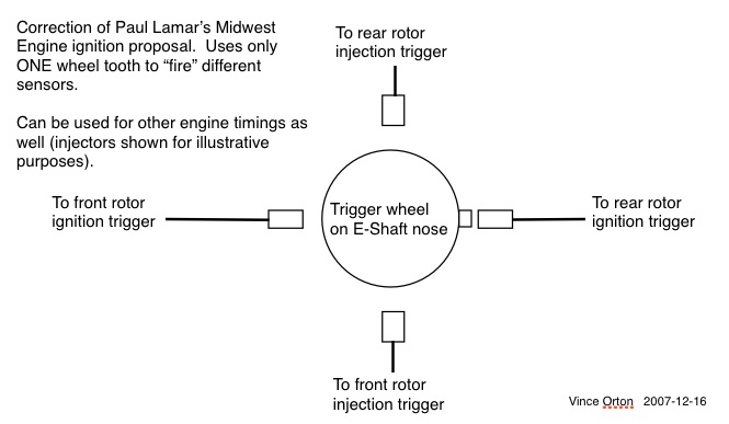
I thought for sure someone would call out Paul on the obvious error in
the "Midwest Simple Ignition" diagram.
He depicts TWO nodes on the trigger wheel. That would fire the both
rotor ignitions every 180 degrees.
I included another diagram depicting a correct implementation of this
idea (using separate sensors for each rotor coil set).
While I was at it, I threw in sensors for other engine events as well
(using injectors as an example). Just taking the idea to it's logical
conclusion...
(By the way, as shown, injecting at 90 degrees BTDC is WAY too late.
Just use this diagram to get the IDEA.)
-Vince Orton
Yes you are right Vince. Thanks for catching that.
Here is the original diagram again with one too many teeth.
However as I recall at the higher RPM's the injector can be
open for an entire revolution (8 ms) or more so 90 degrees before ignition
may not be optimum. As more fuel is needed the pulse gets
wider at the higher RPM's and WOT. As I recall the duty cycle on the
injector pulse width can vary from 10% to 80% and is limited to some
pulse rate which I forgot what that pulse rate is.
"Injector pulsewidth typically ranges from 4 ms/engine-cycle
at idle, to 35 ms per engine-cycle at wide-open throttle."
According to Wikpedia. Obviously at high RPM injector timing
is irrelevant. That also implies a max pulse rate of about
25 pulses per second if my arithmetic is right.
I'll have to go back and research this as we explored
this several years ago as I recall. I think the injector timing
at low RPM can be done in software using the ignition trigger to initiate the
process. That is what I originally intended. Saves two reluctance pickups.
Assume for the moment the back ground loop is incrementing a memory
location starting from zero. The computer receives a hardware interrupt from
the ignition trigger. When the ignition pulses arrives the count is noted
and set to zero again. This gives a count that is an inverse of the RPM.
Large number low RPM. Small number high RPM. Shifting this number
right one bit divides by two giving a count to half way around one rev
or 180 degrees out from the 20 degrees BTDC. When the count reaches
this number on the next revolution the injector can be fired at low
RPM's. You software types can check me on this.
BTW rotaries, unlike piston engines, are on the intake stroke almost
100% of the time. In other words the intake port is always open
except for the brief period of time the apex seal crosses the intake
port. In the PicAXE the pulse width generator is running 100% of the
time and only the pulse width is normally changed by the software
depending on the MAP or mass airflow reading.
Paul Lamar ...No rotor no motor.
The Rotary Engine NewsLetter. Powered by Linux.
ACRE NL web site.
http://www.rotaryeng.net
Copyright 1998-2007 All world wide rights reserved.