George,
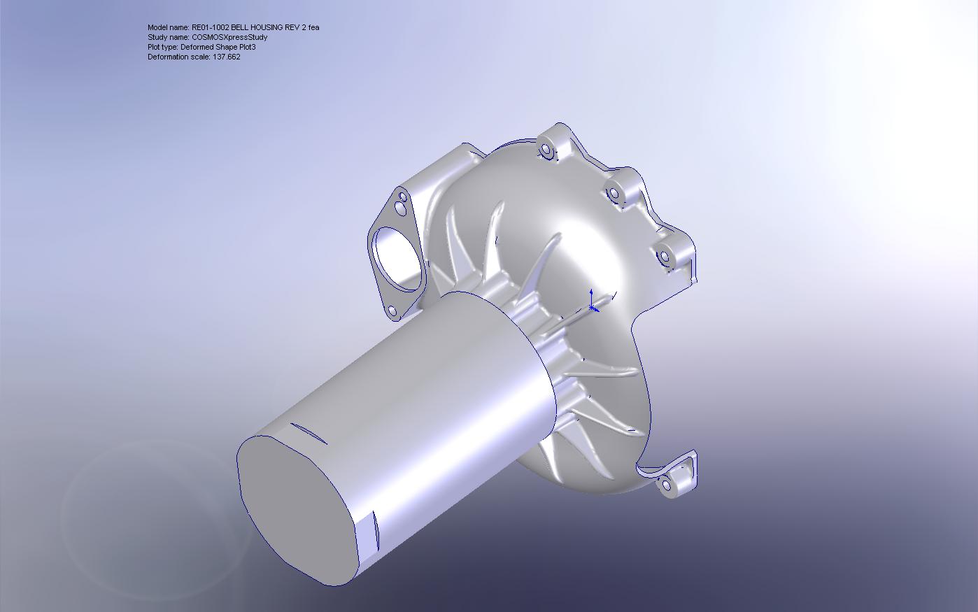
I have attached jpg files from the FEA test. I did do several versions of
this design to come up with one that had minimum stress as well as low
weight. Incorporating the front spacer of Tracy's drive ended up being key
to making this part really strong. It made the outer stiffening ribs much
deeper and they transmit the loads to the outer area of the bell very well.
This design ended with far less deflection than the original design.
The loads applied are 600 foot pounds of positive G load (6G's on a 100 lb
prop, or 12G's on a 50 lb prop), 250 pounds of thrust and 20 pounds of
asymmetric thrust (decending blade theory). The thrust load has nearly zero
impact on the stress loads. The factor of safety on the material is at 1.9
and then only in the upper corner fillets of the stiffening ribs. The total
deflection at the prop hub at this load is 0.011 inches. Stresses are low
with virtually no additional stress from the cutout (see stress distribution
plot).
And have a very Merry Christmas down under!
Larry
-
Paul and Larry,
As I suspected - what is the large missing side section?
George (down under)
George,
The side section is where there is no mounting position on the housing and
allows inspection of Tracy's flywheel mounted isolation bushings. FEA
showed
no negligible loss in strength with this cut as long as the large corner
radius is left in. Saves weight as well.
Larry
Larry,
Not being an engineer, I am probably more concerned than most who have the
knowledge, however I trust you do.
Is this what engineers call an 'air bridge'.
George (down under)
George,
I have attached jpg files from the FEA test. I did do several versions of
this design to come up with one that had minimum stress as well as low
weight. Incorporating the front spacer of Tracy's drive ended up being key
to making this part really strong. It made the outer stiffening ribs much
deeper and they transmit the loads to the outer area of the bell very well.
This design ended with far less deflection than the original design.
The loads applied are 600 foot pounds of positive G load (6G's on a 100 lb
prop, or 12G's on a 50 lb prop), 250 pounds of thrust and 20 pounds of
asymmetric thrust (decending blade theory). The thrust load has nearly zero
impact on the stress loads. The factor of safety on the material is at 1.9
and then only in the upper corner fillets of the stiffening ribs. The total
deflection at the prop hub at this load is 0.011 inches. Stresses are low
with virtually no additional stress from the cutout (see stress distribution
plot).
And have a very Merry Christmas down under!
Larry
The Rotary Engine NewsLetter. Powered by Linux.
ACRE NL web site.
http://www.rotaryeng.net
Copyright 1998-2007 All world wide rights reserved.