Paul,
I installed Electronics Int'l capacitive fuel probes in my Lancair.
They output a PWM signal. I wanted to use the Blue Mountain
EFIS/One to
display fuel quantity in each wing tank. BMA says this won't
work. I
tried using the two frequency channels on the EFIS/One and they seem
work great...on the ground. The problem is that in flight, the fuel
readings gradually increase. Once back on the ground, they will
return
to normal. Needless to say, this isn't good. Others are using a
digital-to-analog converter for this task , connected to voltage
channels on the EFIS, and report that they work fine. Although
they
have reported some erratic readings when transmitting.
I was curious if I could use the PICAXE to read the pwm signals and
output a 0-5v signal to be read by the EFIS? Or, is there a much
easier way to accomplish the task? I would appreciate your
thoughts as
my knowledge of electronics is a bit limited.
Thanks,
Mark S.
14 hrs
Well you need to find out why the readings are increasing.
I suspect the probes. Long aluminum coaxial probes contract when
cold
and electronic devices can drift when the temperature changes.
Where is
the electronic device that converts the capacitance change of
the probes
to a PWM physically located. Best is in the cockpit where
temperature changes
are a minimum. What brand probes are you using?
I read this stuff.
http://www.bluemountainavionics.com/talk/archive/index.php/t-291.html
<
http://www.bluemountainavionics.com/talk/archive/index.php/t-291.html
<http://www.bluemountainavionics.com/talk/archive/index.php/t-291.html>>
Sounds like Greg wants a 0-to 5 volt signal.
No problem using a PicAXE to read, display or condition the PWM data
to a 0-5 volt signal but the D to A part would be the same as
a rectifier (diode) and capacitor. The capacitor and resisters
involved
need to be temperature stable types. There is no direct digital to
voltage (D to A) output on the PicAXE.
It would be much better if Greg's (BMA) stuff took in a frequency or
a PWM
as then the system would be totally digital. A PicAXE could
translate
almost any frequency to almost any other frequency. It could also
translated a PWM to a frequency or vice versa. I would like to
discuss it
with Greq but I don't want to "join his BBS" :) I don't require
people to join
here so he should also not require people to "join his BBS" :)
Paul Lamar ...No rotor no motor.
Paul,
Yes, I'm on the BMA list. In fact, one of the postings you linked to
was from me... (Note: Bob is a BMA tech support guy)
<snip>
07-27-2004, 09:13 AM
Did I miss it somewhere that the EI capacitance fuel probes can be
hooked to the Hi-frequency channels on the BMA, without any
interface/converter box? I have just spent many hours trying to figure
out how to do this and I stumbled across this fact almost by accident.
Seems that this information could/should have been included in the
installation instructions. What I did get (see previous posting) was the
statement, "EI probe transducers are PWM which is not supported by
BMA."
The EI probe comes with a small circuit that converts the signal to PWM,
so I don't need another one, and the 0-5v PWM signal can be read by the
BMA EFIS-1.
------------------------------------------------------------------------
bob
07-27-2004, 09:59 PM
No Mark you didn't miss anything. You can't use the high freq channels
to measure your fuel. You need freq to voltage converters that put out 0
- 5 vdc and wire to the voltage channels.
<snip>
Maybe I should have followed Bob's advice and purchased two of the pwm
to voltage converters? My problem was that it was hooked up and
working, or so it seemed. It still works, if I could only figure out
why the readings aren't stable except when on the ground.
I had not considered the variation being related to temperature change.
These are Electronics International probes which are pretty common with
the Lancair group. I haven't heard of anyone else having this
particular problem with them. They have a small IC incorporated into
the short harness which is attached to the probe with two wires. There
are three wires out of the harness (red, black, & white). I tried
calling EI tech support to get some information on their probes, but
they were less than helpful. So, I attached a scope to the output
(white) and it revealed that it is a pwm signal. I partially submerged
the probe into some diesel fuel (safer than gasoline) and the pwm signal
changed. So, I tried connecting it to the EFIS/One's frequency channel
(normally used for fuel flow) and it read the signal, changing as the
probe was submerged into the fuel, just like it should. Once calibrated
(in gasoline) and it is very accurate. The only problem is the shift
during flight.
As for the location of the electronics, the IC that generates the pwm
signal is in the wing root. I can try wrapping it with insulation and
see if it helps things. If it does, then I will move it into the
cabin. The BMA EFIS/One box is under the back seat, about a foot from
the left probe. So, that would only require a short extension of the
harness.
Something else I hadn't initially considered is to eliminate the PWM
circuitry from the probe and convert directly from capacitance to
volts. Would that be an easier task for the PICAXE to handle? There
are a number of 0-5v inputs on the EFIS box that I could use for that.
A/C Spruce sells a converter (p/n 10-02159) for $50/ea that they say
works on all plate type capacitance fuel senders. Do you feel this
would work? I would have to add a BNC connector to my probes, but that
should be easy enough to do.
Thanks,
Mark
I think we have a definition problem here. Mark.
There is frequency modulation and pulse width modulation.
If you feed a pulse width modulated signal into a frequency
input it will register but it won't work right.
After looking at this chart we need to know if it is really
pulse width modulation or if it is frequency modulation.
Note also that voltages V1 and V2 can vary and not necessarily
go to zero or to 5 volts. The voltages and all the other measurements
can be done with an oscilloscope. Note also the time between pulses
does not change in PWM. Consequently the frequency of a PWM signal
remains constant.
Now I need to know exactly what we are dealing with here as
far as what the level probes are putting out.
--
Paul Lamar ...No rotor no motor.
Mark Steitle wrote:
> Paul,
> I've attached four shots of the scope trace showing the output of
the EI
> fuel probes. I hear what you're saying on frequency vs. pulse width
> modulation. That's why I was surprised when the EFIS registered
change
> as fuel was added. I recently had to drain the left tank. I was
> curious to find out if the left gauge was still in calibration, so I
> left the EFIS on while I drained the tank. Sure enough, as soon
as the
> pump started sucking air, the EFIS' readout went from 0.1 to .0
> gallons. No, I don't understand why it works with a pwm signal
if it is
> looking for a frequency. I guess I really don't need to know
other than
> idle curiosity. If the 555 circuit would do the trick, I'm sure
I could
> build a couple and try them. They look simple enough.
>
> Mark
That is definitely square wave Frequency Modulation and not Pulse
Width Modulation.
Highest frequency period shown looks like 75 microseconds or .000075
seconds
so about that is about 13.3 Khz or 13.3K pps. If my math brain has
not faded. Looks
like the $1.00 Radio Shack 555 trick.
We also need to know what the lower and upper voltages are. I need
to see the
whole scope face and the controls to know what that is. Is that 5
volts per division
or 5 volts full screen? Make sure the scope is set to DC and NOT AC.
It is probably 5 volts per division and we are looking at almost 12
volts
peak to peak. If so it looks like they are running the 555 off the
raw 12 Volt
supply. If so it is dumb thing to do as the circuit might drift with
supply changes.
A 5 volt regulator chip is another couple of bucks.
Now we need to know the frequency range of Greg's Hi-frequency channels
input and what peak to peak voltage it will tolerate.
Paul Lamar
I'm enclosing the BMA EFIS/One installation manual. On page 45 it
indicates that channels 0 and 15 are used for fuel flow and are rated 0
- 220 Hz. These are the two channels that I used for fuel level.
Mark
OK I will take a look later today. Got to go to the hangar.
220 Hz is not going to work with those probes. We can do several
things. Divide it down with hardware is the easiest.
--
Paul Lamar ...No rotor no motor.
Paul,
I'm enclosing the BMA EFIS/One installation manual. On page 45 it
indicates that channels 0 and 15 are used for fuel flow and are rated 0
- 220 Hz. These are the two channels that I used for fuel level.
Mark
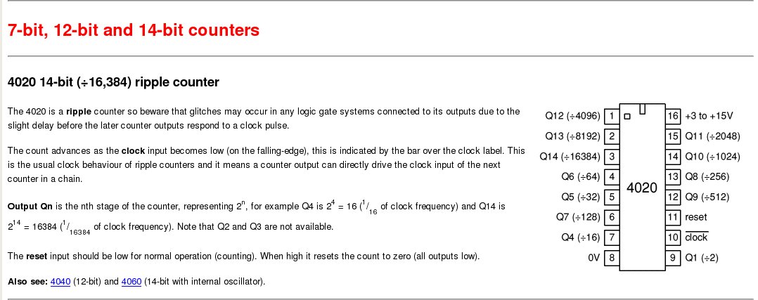
http://www.kpsec.freeuk.com/components/cmos.htm#4017
Get a couple of these CMOS 4020 and fool around with them
until it works. Dividing by 13,333 by 64 (pin 4) will give
about 208 Hz max. Put the square wave signal from the 555
in on pin 10, Take the signal out on pin 4, ground pin 11
and leave all other pins unconnected. DigiKey or Mouser.
If it works tell Greg he owes me :)
----------------------------------------------------------
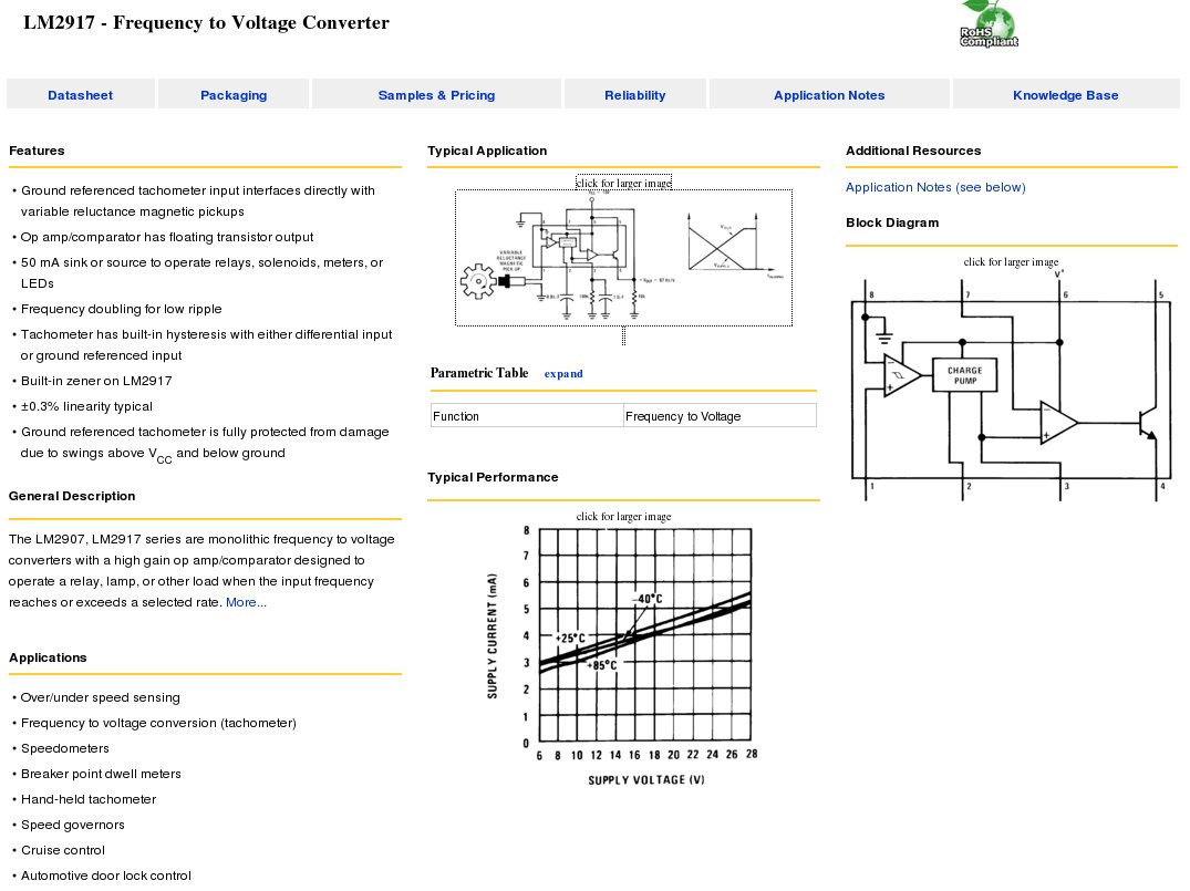
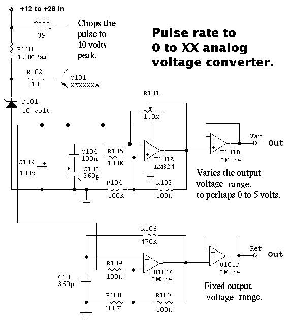
Frequency to analog 0 to 5 Volts Converter.
After you divide it down you can use one of the these and use
the stock 0 to 5 volts analog BMA fuel gage inputs.
Paul Lamar ...No rotor no motor.
The Rotary Engine NewsLetter. Powered by Linux.
ACRE NL web site.
http://www.rotaryeng.net
Copyright 1998-2007 All world wide rights reserved.