> Paul,
>
> I have been secretly working on my fuel gauge/probe problem. I
couldn't
> get your suggested circuits to work (probably my limited
electronics
> ability), so I broke down and purchased two
capacitance-to-voltage
> converters, the same ones used by the Dynon folks and sold by
ACS. I've
> installed one and hooked it to a voltage channel on my efis box,
and it
> works as I would have expected. The sad part is that the new
circuit
> has the same problem as the old circuit in that it drifts in
flight.
> But it returns to normal when back on the ground. That's
telling me
> that something is going wrong with the signal. My guess is
static
> buildup across the wings is affecting the capacitance readings
of the
> probes. How can I check this theory? Any suggestions on
how to
> fix it?
>
> Additional info:
> 1) CTV is mounted inside the cabin (old circuit was in wing
root)
> 2) Pigtail from probe to CTV is shielded (old was unshielded)
> 3) CTV uses voltage a channel (EI circuit used frequency
channel)
>
> My thought at this time is to disconnect the CTV output from the
EFIS
> and connect it to a volt-ohm meter and go fly to see if the
voltage
> reading increases or decreases unexpectedly (drawing off the
other
> tank). This should tell me if the problem is with the EFIS or
the probe
> circuit. I doubt it is the EFIS as other instrumentation
feeding into
> the EFIS is rock solid.
>
> Mark S.
> (rain today)
>
> Interesting theory. Plastic wings as opposed to metal wings.
> Do you have any static discharge wicks on your wings?
>
> One way to check for temperature affects is keep the same fuel
> (about half full) in the wing and check it in the morning
when it
> is cold soaked overnight and again in late afternoon after the
sun has
> its way with the fuel tank.
>
> Paul Lamar ...No rotor no motor.
>
>
> So, just doing a touch and go restores the values to normal? Or
do you
> have to cycle power to the system? Does cycling the power in flight
> have any effect?
>
> If it's static in the tank - caused by sloshing fuel then wicks
on the
> outside won't help.
>
> There are many plastic airplanes that are successfully running
> capacitive fuel probes. I'd think we can get this licked.
>
> Can you doodle out a basic schematic of how the probes are wired
> (including any grounds)? Is one side of the probe grounded or
are they
> both floating?
>
> Might post the question to the aeroelectric connection (on the
matronics
> board).
>
>
>
> Regards,
>
> Matt-
>Mark,
>Do you have a grounding strap into the fuel tank to discharge static
electricity when fueling?
>Bill Schertz
Hi Mark,
I know this is an ongoing problem for you, but could you refresh us with
the condensed version for those of us who have forgotten. Also do your
gage readings show increased or decreased readings while in flight? In
straight and level do the readings fluxuate? Do the readings change in
both tanks and do they do this simultaneously? From what I can remember,
I am leaning toward a possible problem with the physical installation of
the capacitance tubes or the tubes themselves. Dave M
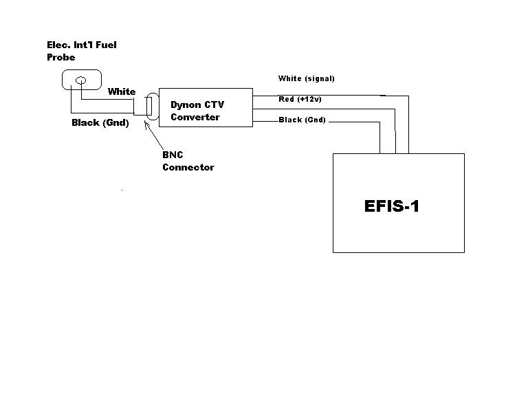
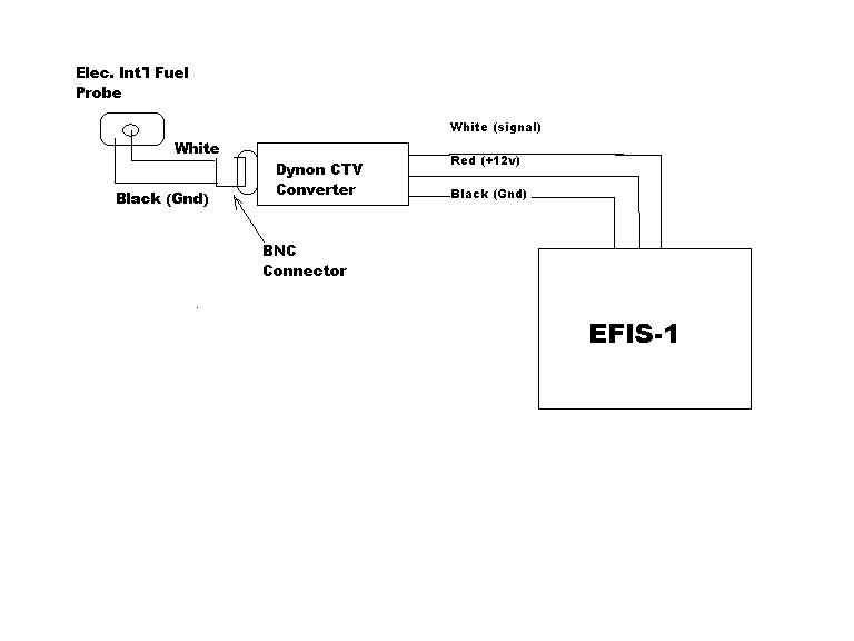
OK, here is a crude sketch of the capacitor fuel probe circuit. The
only thing I didn't show was the two wires between the probe and the CTV
converter is shielded. The shield is tied to the shell on the BNC, no
tie on the probe.
Bill, yes, the filler cap is grounded to the main ground bus. I'm not
sure how many Lancair builders have done that. There is no mention of
it in the manual (big surprise).
Mark S.
Where is the CTV converter physically located relative to the battery?
Paul Lamar
The Rotary Engine NewsLetter. Powered by Linux.
ACRE NL web site.
http://www.rotaryeng.net
Copyright 1998-2007 All world wide rights reserved.