Matt,
I can be heard very well, or so I'm told. My
nav/com is an
SL-30 with a
Bob Archer antenna in the tail. It was tested by a ham
prior to
installation and checked out very well (don't
remember the
numbers).
Coax is RG-400 and is one piece from the antenna all the
way up
to the
radio. The fuel gauges are the only thing that seem
to be
affected by
the radio.
Mark
RG400 is 50 ohm and is for a quarter wave antennas.
http://www.gore.com/en_xx/products/cables/coaxial/optimized_rg400_coaxial_cable.html
Regular Nav/com antennas for metal airplanes are quarter
wave.
"Depending upon height above ground, the influence of
surrounding
objects
and other factors, our quarter wave antenna with a near
perfect
ground
exhibits a nominal input impedance of around 36 ohms."
http://www.electronics-tutorials.com/antennas/antenna-basics.htm
I think what you have Mark is a half wave antenna.
"A half wave dipole antenna does not need a ground plane
and is
nominally 75 ohms."
Despite the fact it is working well this implies some
reflected energy on the outside of the coax shield.
------------------------------------------------------------
http://support.radioshack.com/support_tutorials/audio_video/cable-coax.htm
Cables carried by RadioShack
93-ohm Cables: RG-62, RG-62U
75-ohm Cables: RG-11, RG-11U, RG-59, RG-59U, RG-6,
RG-6U, RG-6QS
51-ohm Cables: RG-9, RG-9U
50-ohm Cables: RG-58, RG-58U, RG-8, RG-8U, RG-8M,
RG-8X--
Paul Lamar ...No rotor no motor.
Paul,
Antennas and feed lines need to be matched with the output
of the
radio. In this case, everything is designed to be
50ohm. If
anything
in the system was the wrong nominal impedance (75 or
93), the
radiated
output would be very low (less than 10% of normal) and the
reflected
energy (SWR) would be very high (>3), and he wouldn't be
able to get
out.
Most aircraft com antennas are modified 1/4 wave - 1/2 wave
would be
pretty big - each radiator would be something like 46" long.
One of the
antennas on this page is probably what Mark has:
http://www.aircraftspruce.com/catalog/avpages/archer_antennas.php
Even if an antenna's length leads to the wrong
characteristic
impedance,
you can connect the antenna via an impedance matching
circuit
(inductor
and/or capacitor). Some antennas include this in the
mounting base.
Since Mark's radio performance is good (and his installation
sounds
normal compared to other aircraft), I'm back to thinking
it's a
vulnerability in the sensor circuit(s). Being a
fiberglass ship
(no
Faraday cage) with the antenna mounted inside the
fuselage, and
without
a ground plane, the electronics in the cabin will be
quite a bit
more
vulnerable to disruption from the transmitting comm.
Regards,
Matt-
Those are very interesting antennas and I agree with what
you said about VSWR. Mark did not say what kind of antenna
he was using. I assumed it was a half wave metal tape.
Many composite aircraft use metal tape antennas as
mentioned in the
Jan 2008 Sport Aviation article.
A half wave would be about 38 inches long. The quarter wave
antennas
are 19 inches long.
If there is a mismatch the coax shield becomes part of the
antenna.
Since it is in the same bundle with the fuel tank wiring the
RF is
probably
being coupled into the fuel tank wiring. It also radiates to
the out
side of
a composite aircraft probably enhancing the antenna pattern.
I was
an antenna technician (among my many careers) in my
younger days
about
50 years ago before I got to be an engineer so I forgot
a lot :)
http://www.microwaves101.com/encyclopedia/vswr.cfm
"Just remember to divide the larger impedance by the smaller
impedance,
because VSWR is always greater than 1. Hey, this
calculation is
so easy
you can do it in your head!!!"
"Let's look at the special case where you mix up 50 ohm
parts into
a 75 ohm system (or vice-versa). In either case, the
resulting VSWR
is 1.5:1. Yes, we did that without a calculator. While we're
at it,
the reflection coefficient is:" "=(75-50)/(75+50)=0.2"
BTW that is less than the 2:1 claimed by the AC Spruce
antennas.
One thing you might have to worry about is what the power
amplifier
does since it is probably designed for 50 ohms coax.
Paul Lamar
19"? Is that at 125MHz (period of 8ns)? Light will go 3*10^8
m/s. 1
wavelength = 8ns * 3*10^8 m/s * 39.37in/m = 94.49in. 1/4 wave =
23.622in. Is 19in based on 2meter (144-148MHz)?
http://www.csgnetwork.com/antennagpcalc.html
Somehow I thought that much impedance mismatch would lead to a
larger
SWR. Thanks.. An SWR of 1.5 is still getting close to only
transmitting half power, so it's not good.
Matt-
Perhaps they have some sort of device to shorten it. According
to the
SA article most UHF antennas are 19 inches. I'll measure the
ones on
my 182 next time I am out at the hangar.
--
Paul Lamar ...No rotor no motor.
I suspect there's some loading circuitry in the antenna.. Just like
rubber duckies are usually 1/4 wave and clearly they aren't
nearly 1/4
wave long. Or, if it's an antenna with dielectric covering,
maybe they
have to be tuned with a shorter length - the dielectric changes the
resonant frequency - making the wire look longer, I think..
Matt-
Mark what kind of antennas are you using? If tape was the coax
connected in the center. I assume they and the coax are bonded in
so there is little you can do about changing anything having to do
with that.
The other thing I am curious about is the new box that converts
the fuel sensor value to a variable frequency pulse. Please look
inside
and tell me the numbers on the chips if they are readable of course.
Some manufacturers mask the numbers sometimes so it makes it
more difficult to copy the circuit.
The diodes Aubrey mentions may be embedded in the chip or chips what
ever the case may be. In that case the only thing I think you can
do is put them in a shielded box and move it away from the coax.
--
Paul Lamar ...No rotor no motor.
Paul (and others),
I made a breakthrough this weekend on the fuel probe problem. I
rewired the right probe with shielded wire from the probe all the way to
the EFIS. Power up the EFIS and Nav/Com, hit PTT, and the gauge is
steady as a rock. The left gauge (the one that I haven't changed) still
acted up as always, but it will be next to fix. But the right one with
shielded wire appears to be working great. It was too late in the day
to fly it, but I feel 99% certain that this has corrected the problem.
Thanks to everyone that shared their ideas and suggestions on how to fix
this very annoying (and potentially dangerous) problem.
Mark S.
25.5 hrs
Congratulations Mark. You had a real bear of a problem there for awhile.
These kinds of problems usually require real expensive instruments
to trouble shoot like field strength meters and VSWR meters.
Probably a good plan of attack is shield everything in an airplane
including all the engine computer wiring.
--
Paul Lamar ...No rotor no motor.
Paul,
I have heard of others having this same type of problem with capacitive
fuel gauges. You would think the manufacturer would provide some
guidance/assistance on how to correct this problem. Oh well, such is
EXPERIMENTAL aviation. Thanks for your help.
Mark
They mostly deal with metal airplanes and they provide a better ground
and some shielding. Also RG400 is the correct coax for metal airplanes
with quarter wave antennas.
I am still curious about your antenna. Did you use a tape antenna?
Send me private email if you want to keep it on the QT :)
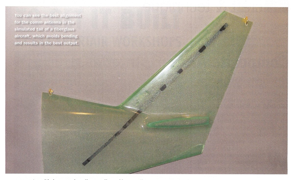
Here are a couple of shots from that SA mag composite plane antenna article.
I think you can just barely see where the coax is connected to the
half wave antenna in the detail photo.
BTW I notice that Cessna bought Columbia so you and Tom Parkes now own Cessna's :)
I also notice Cessna opened a plant in China for LSA aircraft.
--
Paul Lamar ...No rotor no motor.
The Rotary Engine NewsLetter. Powered by Linux.
ACRE NL web site.
http://www.rotaryeng.net
Copyright 1998-2007 All world wide rights reserved.