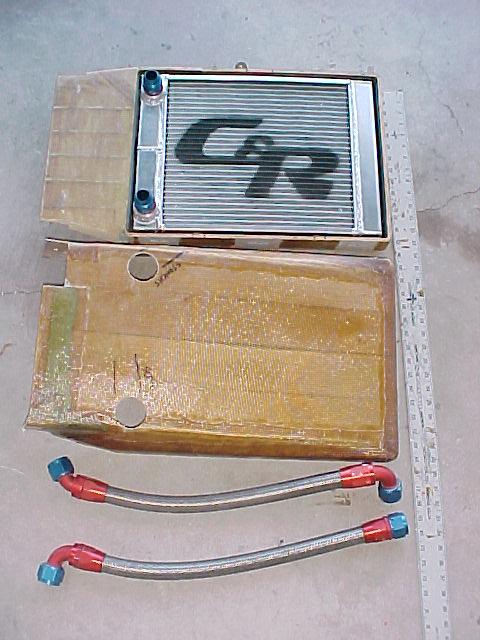
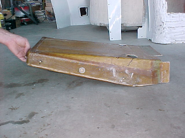
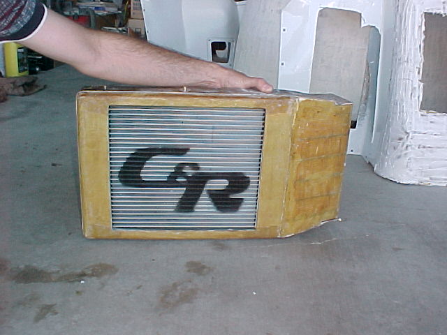
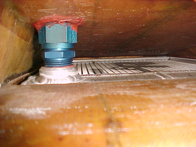
Mark,
So you're not interested in the cooling redundancy that
Paul has
suggested as a good idea - using oil-air and glycol-air
exchangers at
the same time? I still think that would be the
direction I'd
go. In
fact, I'd make that a requirement, as I think it's
something
that could
make for a more favorable outcome should the
airplane suffer
from a
single component failure..
Maybe it's just anecdotal, but the vaunted P-51 Mustang
has a
separate
oil-air cooler, as I believe do the other Merlin powered
aircraft
(Spitfires, Hurricanes, etc). I think the P-40 (Allison
powered) was
the same way.
The Mustang had an induction air to glycol supercharger
intercooler, but
this ran with a separate cooling loop from the engine -
and had
its own
coolant pump and air-glycol exchanger. This allowed
putting the
intercooler where the
directness/compactness/packaging is
important. It
wouldn't be practical to have a duct feeding an air-air
intercooler
between the stages of the supercharger (on a Merlin).
Please keep in mind, I don't have a rotary powered
airplane,
nor a
liquid cooled airplane, nor even an airplane I built
myself, so
take my
ideas with a grain of salt.. :)
I also commend you for putting together an airplane
that's
running
well. I admire the accomplishment.
Regards,
Matt-
Matt,
I do have a glycol-air and an oil-air exchanger, but also an
oil-glycol
exchanger. I don't see where removing the oil-glycol
exchanger
is going
to improve the time I have to get on the ground should the
glycol system
spring a leak. I may explore the possibility of building a
dedicated
exit duct for the oil-air exchanger though... in my
spare time.
If that
works out, then I'll consider removing the oil-glycol
exchanger.
Mark S.
I am really interested in why it is not working better. If
you don't
mind,
next time you are out there, please record the number of
fins per
inch and the
tube spacing. Also if you have a water manometer measure the
pressure
on the face of the oil cooler at speed. Use the porous
foam hot
glued to
the end of the sense tube trick. You have my cooling book.
Here is a chart of dynamic pressure verses speed. The
pressure
should be
.3 to .4 of this number in the center of the core. If it is
higher
or lower
there could be something wrong with the duct or the porosity
of the
oil cooler.
In other words at 120 MPH dynamic pressure is 6.9 inches of
water.
The oil cooler face should be in the ball park of 2 to 2.8
inches of
water.
The higher the number the less the porosity of the oil
cooler.
If it is
blocking the air flow through the core excessively it should
be much
higher
than 2.8 inches.
If it is lower than 2 inches you may have a leak in the duct
or the
duct may
be improperly shaped. You can do the same thing to the
glycol rad
and compare
the two numbers. It would also be helpful to measure the
pressure
behind the core in the cowl as well.
You would not happen to have any data like this on the oil
cooler
would you?
My brain is kind of fried. Pardon the pun. Perhaps
perhaps Bill
Schertz can tell
us where we want to be on the 3 rotor oil BTU rejection.
Paul Lamar
Paul,
Won't the delta-P of the oil cooler be affected by the
properties of the
glycol exchanger and its duct? If the glycol portion has
especially low
drag, I think the pressure inside the cowl will be relatively
high (low
delta-P across glycol exchanger), making it look like there's
something
wrong with the oil exchanger/duct.
I guess if you check the pressure on the front side of the
glycol
exchanger, and in-cowl pressure, and compare all to ambient, you
should
have a pretty good picture of where the air wants to go.
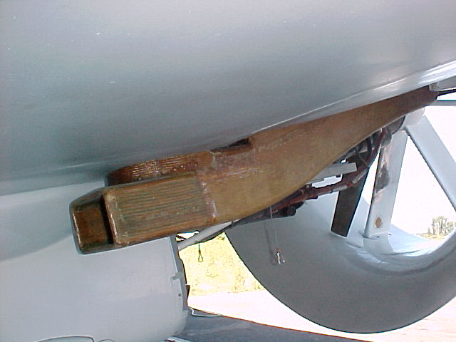
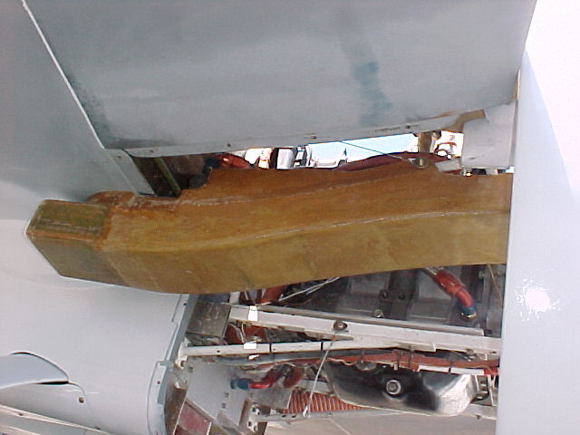
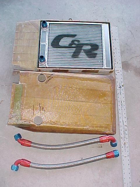
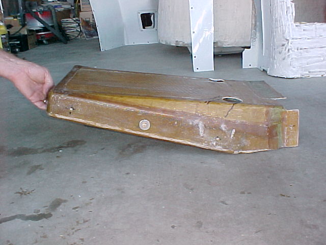
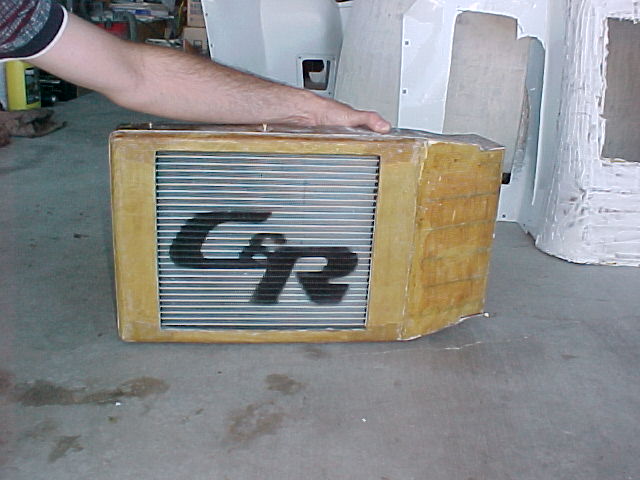
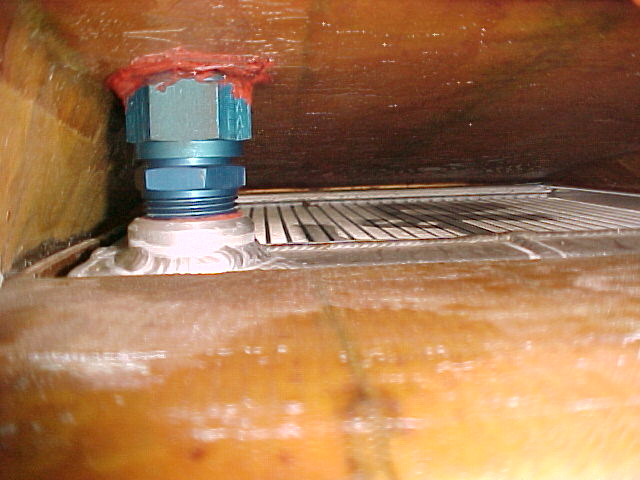
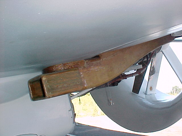
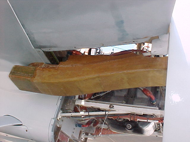
The inlet duct on the oil-air exchanger looks pretty good
(geometry,
shape). If it leaked air, that would lower the glycol-air
exchanger
efficiency (that doesn't appear to be the issue) by raising the
in-cowl
pressure. So, it seems like the oil-air exchanger might not
be well
matched to the glycol-air exchanger - when feeding a common
outlet
chamber. If this is the case, the only fix I can think of is to
arrange
for an isolated outlet from the oil-air exchanger. You could
also block
a portion of the outlet of the glycol-air exchanger, but that
seems so
wrong.. :)
Mark, is your cowl in final paint? I think it would be pretty
easy to
cut louvers aft of the oil-air exchanger, build a small outlet
plenum
and connect it to the outlet of the oil-air exchanger with large
diameter scat tube. Maybe it would look something like this:
http://www.cs-ent.ca/6578o.jpg
If it doesn't buy you anything, you wouldn't have spent much on
it, and
they'd be easy to cover over later (assuming you aren't in final
paint).
Regards,
Matt-
Best to put a small flap on there to keep the oil temp up
at high altitude cruise. Reduces the GPH.
--
Paul Lamar ...No rotor no motor.
Sure.. I was just trying to come up with a cheap proof of
concept. A
cowl flap would be ideal. Could even be controlled by a picaxe
or maybe
simple a sealed bellows..
Matt-
VW thermostat. BTW it sucks air through the oil cooler when wide
open.
Paul Lamar
Yes, a/c is still in primer. I'll see what I can do on this. I'm
pretty sure Lancair sells fiberglass gills that I could bond onto
the lower cowl. That's just what I wanted... more fiberglass work.
Mark S.
Make some measurements first and see if it is not something else
such as an air leak in the input duct. The less porous the core the more
important the input duct air leaks.
Use thin wood ply door skins from the Home Depot to make the duct.
Then cover
them with glass. Quick and easy.
As far as I know three people have been affected by coolant leaks. Two
tried to turn back to the runway and crashed and one landed on the
freeway.
Non fatal crashes.
When water turns to steam it expands something like 6000 times as I
recall.
What happens next is the pressure cap over pressure valve pops off
and the steam pumps the remaining coolant overboard in seconds.
Not something you want to fool around with.
Use a cowl flap Mark.
It will enhance the flow through the oil core during take off and
climb out.
Aero drag matters not on climb out. Much of the HP just goes to lift
the weight of the airplane. 2500 pounds at 1000 feet per minute is
is 2,500,000 ft pounds per minute. Dividing by 33,000 foot pounds per
minute which is one HP equals 75 HP just to lift the weight of the
aircraft
alone not counting aero drag. If it is 1500 FPM it becomes 112.5 HP.
The induced
aero drag also increases due to the higher wing lift coefficient
required.
I know you know most of this as you have my cooling book so this is
primarily
for the new guys.
Paul Lamar ...No rotor no motor.
> Paul,
>
> I was very careful when fabricating the inlet duct to ensure a tight
> fit, which it does. But there is a small hole or two at the corners
> that could use a dab of silicone. I know it doesn't take much to cause
> a big leak, but the holes I'm referring to are very small. I'll plug
> them and see if it makes any difference.
>
> Good idea of using door skin material for a form for the duct. Of
> course, it needs to be covered with packing tape or some form of release
> agent or it will be forever married to the fiberglass.
>
> Mark S.
>
Put some duct tape over the piano hinge as well.
You leave the door skin in there. It is very light weight sandwich and it is stiff.
Almost like balsa wood core. I learned this trick from Perry Mick. You only need
one layer of glass cloth. Actually 4 oz glass cloth would be OK if you can find some.
--
Paul Lamar ...No rotor no motor.
The Rotary Engine NewsLetter. Powered by Linux.
ACRE NL web site.
http://www.rotaryeng.net
Copyright 1998-2007 All world wide rights reserved.