> > Hi Bill,
> > There may be a potential pitfall to your idea. The axial flow blade
> > shape (twist, airfoil shape, length) would have to be optimized for a
> > particular gas flow. That would mean a bell curve for efficiency.
(There
> > would be down slopes either side of a particular point.) As you go to
> > altitude, less and less gas would be produced so a design
optimizing the
> > bell curve high point that works well at sea level will not be the
> > optimum at altitude. Some compromise would have to be allowed for. The
> > most logical scenario would be to design for 8000 feet at whatever gas
> > pressure is available from the engine at that altitude. Above 8000
> > you're WOT and nature will decrease gas flow as you go higher , and
> > below that level the pilot can maintain gas flow if
> > the additional performance is required. The downside here is that to
> > receive 'compound' fuel efficiency benefits at say 3000 ft the
aircraft
> > has to be operated at WOT which may not always fit the flight
> > mission. Dave M
>
> All the more reason to put a turbo charger after the turbo-compound
> turbine so that you turbo normalize the engine. Who doesn't want their
> available power at altitude to be close to full?
>
> -dave
>
> The ideal configuration is have the turbine and the compressor on the
> same shaft. That minimizes heat and kinetic energy loses.
>
>
> Paul Lamar
Is that right (ideal configuration)? It sounds like you are saying a
single stage turbine is more efficient than a multi-stage turbine.
That's not true for jet engines.. Maybe that's an apples to oranges
comparison..
Matt-
What I am trying to say is there are heat loses and kinetic energy loses
in the plumbing on the typical dual turbine, turbo compound installation
such
as DD, Scania and Caterpillar.
Some multistage turbines are on the same shaft.
Perhaps the best configuration is have the blow down turbine
on one shaft and the compressor turbine on another both turbines
in the same housing to minimize heat loses. Perhaps coaxial shafts
can be used. This is done in turbo fans. The first smaller turbine
drives the compressor and the larger diameter second turbine drives
the fan. In our case the second turbine could be the power turbine
for the turbo compound part. Power for the TC could be taken from
the center of the turbo charger so to speak. Much like the Napier Nomad.
Obviously an engine years ahead of its time :)
All this is moving further and further away from Bill Jepson's KIS.
-- Paul Lamar ...No rotor no motor.
Paul,
From your comment you obviously "got" my idea. The idea here is a
proof of concept ULTRA SIMPLE idea using NO Turbocharger, only
an axial flow turbine. Accepting that the system would only be optomized
at one RPM and altitude and being happy if it didn't mess up the rest.
Just concidering the turbine as an exhaust restriction the rest of the time.
On another front here, why would it be advantagous to be in line with
your turbocharger with your power turbine? They are independent shafts.
A very short connector from the TC's outflow on a turbocharged machine
is desireable, but otherwise who cares? The idea here is almost stooopidly
simple. The paddlewheel in the millrace type of thing. ANY power recovered
is a bonus and you can get by with a much simpler muffler. Since we would
normally run the engine up to at least cruise RPM static before takeoff you
would always be recovering some of the exhaust hp. Think of it as a "magic
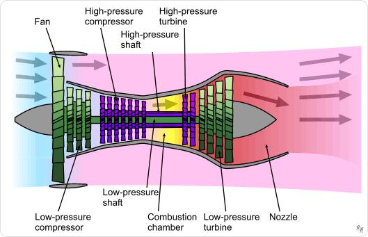
muffler." Paul you found a great cutaway of an axial flow turbine, which
I lost.
Do you still have it? This could be done on a normally aspirated engine,
in fact
it would be easier that way.
Bill Jepson
Is this it?
Paul Lamar ...No rotor no motor.
The Rotary Engine NewsLetter. Powered by Linux.
ACRE NL web site.
http://www.rotaryeng.net
Copyright 1998-2007 All world wide rights reserved.