Paul,
Do we have anyone on this newsletter with experience with engine testing
within a hypobaric chamber? I am curious to know how they work.
I believe the chambers would have to have a means of blowing in fresh air
while sucking the exhaust out at a greater rate than the input air to
keep
the chamber at partial vacuums.
With the Poor Mans hypobaric Chamber, PMHC, lets us say that our
purpose is
to only test how much the recovery turbine increases in power at higher
altitudes. We won't have to test heat exchangers and electronics
because we
are confident our over-designed systems will function well at high
altitudes. Yea right:) In any case the oil and water cooling is handled
remotely like on standard dyno set ups.
Background info:
A turbocompound engine must be boosted for the recovery of energy to
occur.
Let us assume we want to test the traditionally turbocompounding method
first. In operation both a supercharger and blow down turbine are
connected
to the drive shaft albeit in different locations. The supercharger is
taking
energy from the drive shaft and the blow down turbine is putting that
loss
and some 'plus alpha' power back into the shaft. In other words there
is a
net gain. Sort of like 'compounded interest'
Testing:
First the supercharger. Factory test data curves showing power
consumption
at different pressures and airflows can be confirmed by running the
supercharger connected to a large electric motor and confirming the
results.
By the putting a torque arm on the free-to-rotate blower, and running it
through a manifold simulating the manifold resistance, the compressor
becomes the load. Temp., pressure, and air flows are documented as well.
Running the intake through a hypobaric (partial vacuum) chamber of
lets say
a 10 cubic foot thick steel pipe with a control valve set on the
intake set
to maintain a certain partial vacuum might work I think.
Second the exhaust.
Now imagine the exhaust pipe is connected to our test turbine and from
there into a another pipe hypobaric chamber. Connected to the outlet of
this pipe would be a blower which was reversed so as to suck. This
powerful
vacuum unit will be driven by the same supercharge 25kW 3phase
electric test
motor and interfaced with a vacuum sensor set to keep the exhaust
hypobaric
chamber at 14.95" of Hg if we were simulating 18,000 ft. Running the
test
in winter would give us our low STP intake temperatures.
Let me back up and say that this testing would be done only after the
engine
is running stable and in the boosted conditions. Next the blowdown
turbine
needs to be connected to a dyno. After the output is confirmed from
different turbines we can connect the best candidate to the drive shaft.
So what are we testing here? We can understand that at a given CFM of
air
input, MAP, and altitude, how much power the blowdown turbine is putting
out. We hold the altitude and vary the MAP and/or RPM and note the
results.
In short we know how the turbine's will perform at increasing high
altitudes.
Now if the goal was to test a turbochargers at altitude than this system
would work as well. We replace the supercharger, with a turbo charger and
compressor, and either a flexible shaft from the compressor to the
dyno set
or the turbo exhaust to another blow down turbine and then dyno.
I would appreciate comment on any of these premises.
Sincerely
Doug in Japan
You could test at the top of Pikes Peak or mount Fuji.
Or you could rent Pratt & Whitney test chamber.
Paul Lamar
It was a surprise to me P & W doesn't care what happens post engine. Of
course our engine doesn't matter as much as theirs does about the
velocity entering the engine, but T & P we also care about. The car
makers here all test their cars at Pike Peak, particularly the towing
ratings. Are there road up Mt Fuji ?
-dave
Dave,
There is a road up to the fifth station of Fuji at 2300 meters but none to
the top. I believe they had to bring the weather station dome on top by
helicopter. Mt Fuji is rugged and very exposed. Winds can and often do
literally blow people off the mountain. I was lucky to climb it on an autumn
day devoid of both wind and people.
http://www.japan-guide.com/e/e6901.html
I will haul the engine complete with cowlings, and heat exchangers inside
the fan drive wind tunnel dyno up to altitudes for the final testing, but
now I am at the a turbine sizing planning stage.
About simulating high altitude testing, I reasoned that the input mass of
gases and fuel is equal to the exit mass of gases but the temperature of
the gases and the volume of gases increase.
I don't fully understand how the ICE test chambers work but I reasoned that
they must allow the exhaust gases, to expand completely and then pull them
out of the chamber with engine heat using huge exhaust fans. Their biggest
inputs of energy to run the chamber then is in exhausting the chamber at a
faster rate than the air comes in as well as the cooling loads for providing
the make up air. It is hard to fathom the amount of energy that is needed to
test a jet engine at a simulated 65,000 feet.
I am now just concerned with testing the performance of one exhaust turbine
at at simulated altitude. Can we computer model turbine performance at
altitude? Perhaps if we had some data from turbo makers but that is like
pulling teeth.
On the input side of our engine we test at a temperature equivalent to what
we know exists on a STP day at our test altitude. We use nature as it is
expensive to create the large and constant volume of refrigerated air we
need. This means winter testing. Giving this matter some more thought, since
we already know the performance of our compressor at different altitudes we
can downgrade its performance by altering it to match the expected
performance at a given altitude. Perhaps we can choke the inlet and/or bleed
air after the compressor. This takes care of the input side.
On the exhaust side I'm not sure. We would have to make the exhaust think
it was exiting the pipe into a partial vacuum atmosphere. Could this be
accomplished before the gases are expanded by pulling a partial vacuum on a
tee junction out near the final end of the exhaust manifold? High
temperature would be the challenge so we would run a turbocharger in reverse
via a electric motor. Just upstream we would need a way to measure the
ambient pressure and a feedback loop to control either the electric motor
inverter or a solonoid operated bleed valve. Our testing would be done in
the steady state manner because with such small pipes, high velocities, and
high temperatures, the challenge is daunting.
Ah well... Back to the drawing board.
Doug in Japan.
Doug, contact Barber Nichols for turbines.
http://www.barber-nichols.com/email_us/
engineer@barber-nichols.com
Don't tell them I sent you.
Make like GM or Toyota.
--
Paul Lamar ...No rotor no motor.
Paul,
Ok I will contact them incognito:) Would you be kind enough to give me the
exhaust velocities and pressure we will expect at 220 hp power setting?
Assume a P-ported 5 psi boost, 13B with a 9.8:1 compression ratio. @15,000
feet with E-85 fuel. Also assume the turbine will have a short manifold as
possible to keep it close. I propose the TIT should be kept below 1650 F.
E-85 lowers the combustion temp. about 100 degrees.
Thanks
M. Lie Ng
General Manager
Rong Way Industries
I'll do it for a P-port NA rotary engine first at sea level. Turbo charged
at altitude is more complicated. Here are the basics. You can go from here.
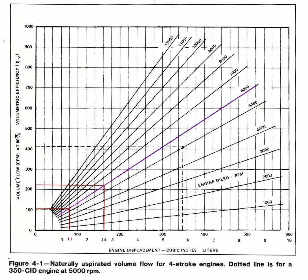
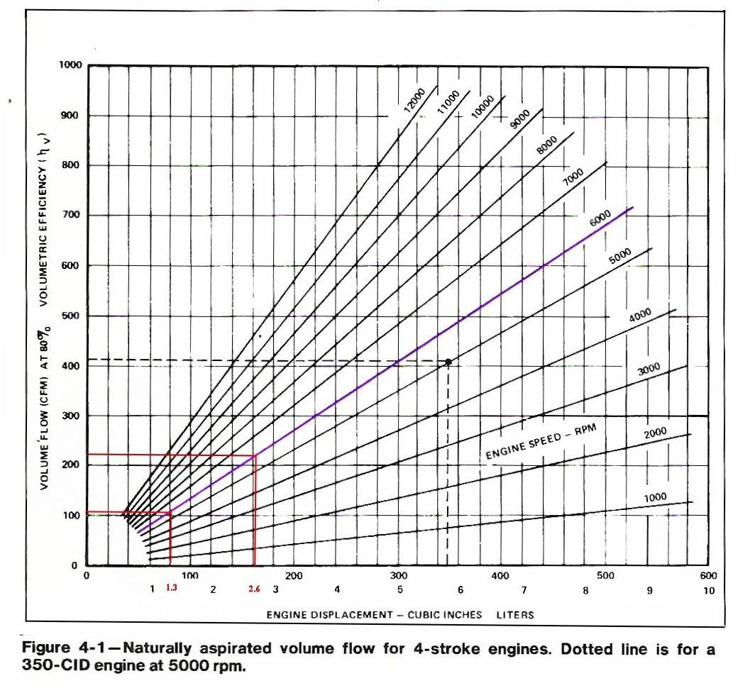
A 13B pumps the same air as a 2.6 L piston engine NA. See chart.
Assume the intake pipes and the exhaust pipes are the same 2 inch diameter.
A 120% VE p-port rotary is taking in 120/80 times 220 CFM or 330 CFM at 6000 RPM.
What goes in must come out.
The ideal gas law is (P1 x V1) / T1 = (P2 x V2) / T2
http://hyperphysics.phy-astr.gsu.edu/hbase/kinetic/idegas.html
P is pressure in pounds per square foot.
V is volume in cubic feet.
T is temperature in Rankine.
http://www.onlineconversion.com/temperature.htm
Where the ones are in and the twos are out.
You need to calculate the velocity in the intake pipe
based on the area of the pipe in square feet. Lets say it is
a 2 inch diameter pipe with an area of 3.1416 square inches.
Pi x R squared. R is one inch.
Area in square feet is 3.1416 / 144 or .0218 square feet per pipe.
Two pipes so total area is .0436 square feet.
Velocity going in is therefore 330 / .0436 or 7569 FPM or 126.15 FPS
or 86 MPH.
You need to calculate the increase in velocity in the exhaust
pipe assuming the exhaust pressure is atmospheric or the same
as the intake pipe.
Assume T1 is 140 F or 600 degrees Rankine.
Assume T2 is 1700 F or 2160 Rankine.
All other things being equal it is merely T2/T1 times velocity intake
velocity or 2160 / 600 times 86 MPH or 309.6 MPH.
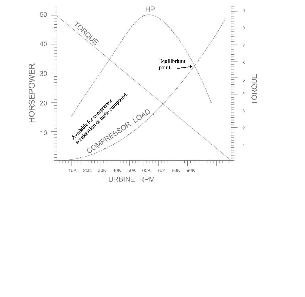
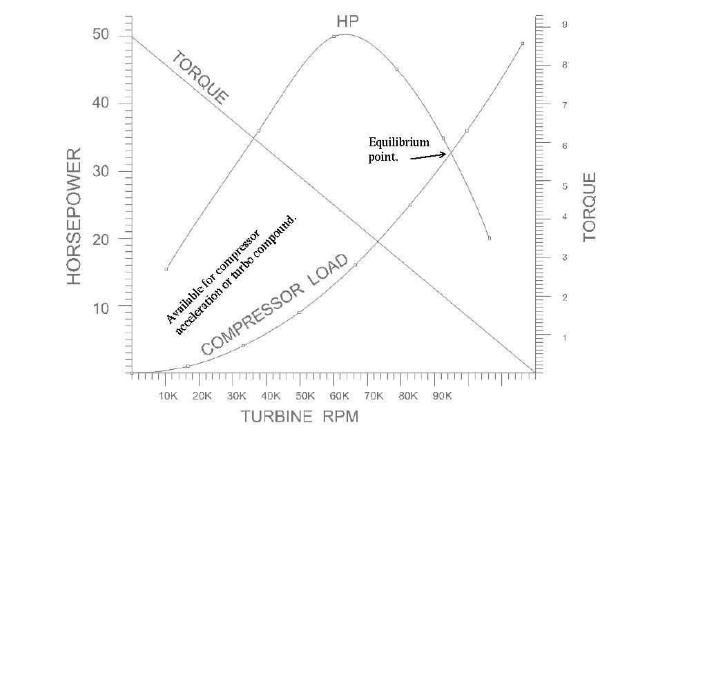
Max HP of a turbine happens when the blade velocity is about half the gas velocity.
See the chart. The impact pressure on all the blades per square foot is .0026 x MPH squared
given sea level air density from memory. You need to total the blade area in square feet.
Knowing the turbine radius you will know the torque on the turbine and it's RPM
and the blade velocity. The relative gas velocity impacting the blade will
be about the same. You want the blade velocity to be about 155 MPH. The net pressure
on the blades per square foot is then the dynamic pressure which is .0026 times 155 MPH
squared or 62 pounds per square foot. This does not count atmospheric pressure
which we assume is the same on both sides of the blade. A piston engine would
slow this velocity somewhat due to the exhaust valve. The kinetic energy available
would be about half compared to a P-exhaust port rotary. I am
basing on the SAE R3350TC paper written by Curtis Wright.
I'll leave calculating the blade area and turbine diameter and RPM to you
or Barber Nichols. Assume the lift coefficient on the blade is one
for now. It may be as high as 1.5. Check with Barber Nichols. Please
report back on that.
You will need to make some assumptions about the exact cross sectional
area of the axial flow blades their number and their weight. The centrifugal force on
the blades is m x V squared over R. Make the blades hollow as that reduces
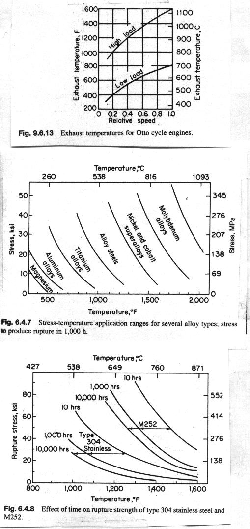
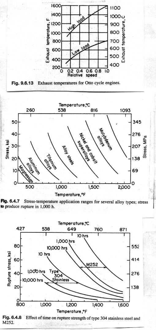
the mass and cools them from within just like the R3350TC. The max stress the blade
will sustain depends on the temperature of the blade and it's max allowable stress
at that temperature. Here are some data on that. See the chart. This is the factor
that will limit the length of the blade. I suspect the ideal blade would be
tapered and twisted slightly.
Now this is for no turbine nozzle increase or decrease. A nozzle can speed up the
exhaust velocity or slow it down depending on what you want. If you speed it up it
will increase the back pressure on the engine and if you slow it down it will decrease
the exhaust back pressure on the engine. You must come up with a compromise that gives the
best net HP out of the engine/turbine combination. There is evidence from this old
NACA turbo compound piston engine report 822 that some nozzle contraction and increased
back pressure results in the best overall HP out. The very best thing to do is use
a variable nozzle area device.
Also there is about a five percent increase in these numbers due to the weight
of fuel injected.
BTW if a small amount of water is high pressure injected into the exhaust manifold
it will turn to steam by expanding over 6000 times (as I recall) and increase the
exhaust gas speed and cool the exhaust at the same time. Probably with a net increase in
turbine HP. If you preheat the water by passing it through the cooling
system first you will recover some small part of the waste heat in the cooling
system. The closest anybody will ever come to burning water :)
Let us know what you decide.
All you physicist out there check my physics and arithmetic.
Paul Lamar ...No rotor no motor.
The Rotary Engine NewsLetter. Powered by Linux.
ACRE NL web site.
http://www.rotaryeng.net
Copyright 1998-2007 All world wide rights reserved.