Paul;
Here is the report on my airflow measurements. It is a bit long, and you can
break it up as you like. Or I could get it uploaded to my website, and
provide a link. (BTW, you can put me back on the list and I can field some
questions and comments.
Some of you may recall that I brought up the issue of marginal oil cooling
in my Velocity 20B last fall after finding that I was limited in climb rate
in the warmer summer weather. I continued to enjoy flying during the cooler
winter months, and it hasnt been much of an issue. Now as we approach
summer again, I intend to institute some changes. Before doing so I wanted
some further data on the air flow.
The cooler is in the wing root; behind the strake, behind the spar. Inlet is
under the wing behind the main gear door cover. The cross section of the
inlet is shown in the Attachmt 1. The sketch shows the original shape when
pressures A (ram, in front of scoop), B and C (static) were made. I then
modified the upper profile as shown, and sealed all the gaps around the
cooler, and measured the pressure at D. Cooling improved very slightly.
The exit above the wing is shown in attachmt 2. A pressure measurement at
the mid point of the outlet was about -1 of water somewhat disappointing
since the theory was that there would be lower pressure there.
I had concluded that the airflow in front of the scoop was being somewhat
disrupted by the gear door, which does have a bump on it for the wheel
toward the out-board portion of the entry scoop.
Paul Lamar was kind enough to ship his multi-manometer setup (attach 3) to
me so I could get some more data. One challenge was to find ways to get
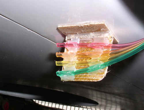
many tubes from the measuring point to the manometers. Some 4-wide color
coded clear 1/8 ribbon tube from McMaster-Carr helped facilitate that. I
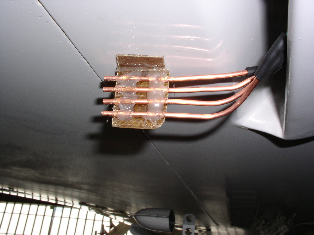
then fabricated a couple of velocity rakes (attach 4, also one from 1/8
copper tubes), and we measured 8 points at one time. The tubes are at 5/16
spacing.
The wide inlet scoop (23) is divided into three sections. We placed one
rake at the middle of the in-board 1/3, and one at the mid point of the
outer 1/3 (this one behind the bump in the gear door). We then took
measurements at 120 KIAS climb (138 mph), and at 150 (173 mph) level. The
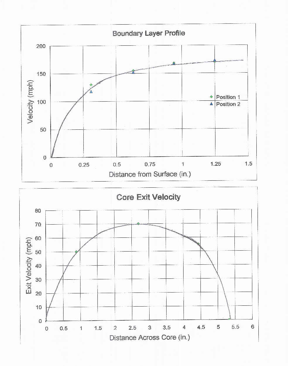
results for 150 KIAS are shown on the upper chart in attach 5. I penciled in
the curve to the 5 points including 0 at the surface. (I should point out
that the measurements were made on the opposite wing which has a matching
radiator installation, and still has the original non scoop inlet, in order
to facilitate running the tubes. The location behind the gear door is the
same.)
The result shows a fairly normal boundary layer profile; at both positions.
The low velocity portion is less than ½ thick which is consistent with that
computed by a little BL program that I have. The scoop extends into the
airstream about 1 ¼, at which point ther is essentially free stream
velocity. What does it tell me?
1. My assumption that the BL was somewhat mixed and turbulent was not
correct.
2. Segmenting the profile and determining an average velocity (about 135
mph) would give me very close to the desired air flow rate IF the scoop were
operating at 90% efficiency.
It was also interesting to find the profile shape changed little with the
planes airspeed, however; the profile at the lower speed was more like 20
mph less, when the planes speed was 35 mph less indicating a slightly
higher pressure under the wing at the higher AOA.
OK, that was fun. Next we set up to measure the air velocity profile at the
exit of the core. This was done by positioning 1/8 copper tubes as pitot
tubes close to the surface at different positions across the core, near the
center of its 22 length. That result is shown in the lower chart in
Attach 5.
Clearly the flow is not very uniform, being quite highly peaked toward the
center. This of course indicates the diffuser is not being effective.
Again, by segmenting the profile, and adjusting to the actual flow area
(minus the tube area, but not accounting for the fins), I could compute the
approximate total flow rate through the core. It is about 68% of the
potential inflow for an effective scoop- telling me that some amount of air
is flowing around (under) the scoop.
Two other relavent pieces of info: we measured the static pressure on the
upper surface outboard of the outlet fairing, about 1/2 off the surface. It
was consistent with the earlier measurement behind the exit fairing (about
-1). We also tufted the back edge of the exit fairing with some 4
strings, and noted that they went straight back indicating the air cleanly
detaching at the edge, and no swirling down into the exit stream. These
things suggest that the exit fairing is not inhibiting the flow. It is also
not enhancing it, but does provide protection for the core and looks
pretty coolg. We did not tuft the surface of the wing behind the fairing
because that is not visible from the cabin. We also did not use longer
tufts because these were the longest we could scavenge from the dust mop,
since the tufting was an afterthought and we did not come equippedg.
So-o-o-o; before going into these measurements, I had pretty much decided to
install an oil/coolant heat exchanger since my coolant temps run 20 40F
lower than the oil, and have some margin. That is a fairly major mod to the
plumbing. Trying to modify the air inlet to get more effective diffusion is
also major, as it requires removal of the wing and the oil cooler. This
would require some reshaping, and a baffle(s) the width of the scoop to
confine the slow BL to the upper portion of the inlet. And how effective
it could be made within the confines of the wing root, and ingesting the BL,
and without adding drag - is uncertain.
Therein lies the dilemma.
BTW; the placement of these coolers in the wing root in this manner was
based on the testimony of another Velocity builder you had placed his Lyc
oil cooler there, and said it worked great even without a scoop because
of the pressure differential above and below the wing. I dont know why his
experience was so different, but it does not surprise me that there isnt
much differential since the stake area on a canard airplane is basically
neutral in level flight.
Anybody read this without falling asleep?
Al
Good work Al. Thanks for the report.
--
Paul Lamar ...No rotor no motor.
The Rotary Engine NewsLetter. Powered by Linux.
ACRE NL web site.
http://www.rotaryeng.net
Copyright 1998-2007 All world wide rights reserved.