Matt--we did first try a mechanical fuel injection pump on the first
SuperLight engine, with the pump driven by a gilmer (cog) belt. All
subsequent engines used dual electric pumps. There is an worthy sub-note
regarding our experience with the engine belt-driven fuel injection
pumps.
When we started running the first engine (a dual side port with aluminum
housings) we started immediately having torsional issues. When we would
run
the engine and planetary reduction gear on the water brake dyno, at
certain
rpm, under certain conditions, the belt would blur and jump teeth. This
was
prior to shearing the engine/dyno spline. Bigger shaft/spline and same
thing happened again.
These torsional issues were later resolved with
pendulous dampers on eccentric shaft when using planetary reduction
drives
and then to torsionally stiff internal spur gear reduction gear finally
to
eliminate the neeed for the pendulous dampers. But first indication of
torsional issues was the belt drive blurring on Hilborn fuel injection
pump
at certain rpm.
Paul--as to your question on running lean of peak.
In flight testing we generally operated the engine lean of peak at cruise
power.
On the first SuperLight prototype, we made a continuous flow, fuel
injection system with direction injection nozzles (deflecting off the
rotors
in an attempt to get better vaporization and some hopeful
stratafication).
This allowed us to run the engine the leanest of any engines we made. A
part of this was probably due to placement of injectors and other issues.
We experimented with a myriad of nozzle positions and we can go over the
pictures if you want.
I earlier saw some of my knee-board flight logs on
this early engine but can't locate them now. Will keep looking. What I
do
remember most about this system was the configuration produced the very
leanest possible mixtures to an almost goofy level. Below 5500 rpm you
could
lean it to where it simply started to lose power by putting the fire
out....
in the low 1300 EGT degree range with no ragged misfire.
For comparison,
EGTs on the dyno at best power were as follows--1480 EGT @4,000 rpm/
110hp;
1500-1525egt@ 4500/135hp; 1600 egt @ 5000 rpm/160 hp; 1620-1650 @
5500/180
hp; 1620-1690@ 6,000/180 hp. With this system and the jetting the notes
show we were a little rich at the higher rpms on these dyno runs.
A part
of the cruise anomaly may have been related to the fact that back then
our
cruise rpm was very conservative because this thing was fresh off the
paper
and we were very incremental in raising sustained three and a half hour
flight legs. In those early development phases we were generally
cruising
in the low 5,000 range. We were running an 84" prop.
The later engines and systems could not be leaned as aggressively without
a
substantive misfire. On the last conversion Mazda engine, WOT @ 7,000 rpm
at
2500 ft/OAT 65F at best power produced EGTs of 1700 front and 1650 rear
using rotor direct injection. This was 235-239 mph in the RV-3. In the
same aircraft, notes show 6500 alltitude @ 5900rpm leaned to best power
1500 front and 1600 rear. Some dyno numbers for the SuperLight engine
installed in the aircraft @ 5500 rpm was 1650-1700 leaned to max power
and
1500-1600 full rich.
At cruise, a flight log entry at the same engine at
5,000 rpm max lean was 1400 EGT (OAT 45F). On the dyno in the last
SuperLight engine recorded 1410 and 1430 EGT at 5200 EGT full rich. But
the
dyno numbers in isolation do not mean much. We were simply changing so
many
variables at the time. All data logging back then was manual. All the
above numbers were with the AirFlow Performance fuel controller and our
homemade venturi for the signal.
In the fall of 1995 I flew the RV-4 with the Mazda conversion engine to
Montana on a business trip and have the following numbers: lean of peak
5,000 rpm @7500 ft , EGT 1500&1550; 5200 rpm 1500/1600. Final leg of
that
return flight Nampa to Hatch International @5600 rpm, 10,000 msl EGT's
were
also 1500 and 1600.
But an important footnote to these numbers was the
engine had to be operated with a retarded throttle to prevent misfire
regardless of rich/lean. We earlier had moved the nozzles in the rotor
housings (various locations) during this period in an attempt to address
this issue. We were consitantly plauged with a misfire on takeoff and
cruise at WOT which could be cured only by retarding the throttle. This
would occur from sea level to over 10,000 ft. Alan's flight notes show
the
same thing.
Finally we stumbled on a cure. In desperation, we moved the
fuel injection nozzles from the direct injection location in the rotor
housings to the induction tubes right at the base of where the induction
tubes entered the periperal port, just outboard of the throttle plates in
the housings. We had brazed these ports into the tubes earlier to
provide
supplemental nitrous fuel nozzles. This completely fixed the WOT
misfire.
Unforturnately we didn't have time to get good data in this location as
Everett was killed shortly thereafter. Our subjective analysis was that
the
engine made more power with a higher fuel burn. But that is probably
skewed
by the fact that we were testing an in-flight adjustable propeller that
was
allowing us to develop full power at takeoff and WOT operation at
cruise.
So no good data set in that configuration.
We are using the exact same
constant flow/nozzle configuration on the engine we are now building for
the
new RV-3. We are using the same configuration nozzles/sizes with nozzles
in
the induction tubes, Airflow Performance fuel controller and our venturi
in
the plenum inlet. This is exactly as configured in the engine in the
RV-4
at the time of the crash. We are hopefull this will give us some good
numbers in the future from both the dyno and in flight tests for the
folks
who have interest in this type of lower tech old school system.
We
assembled the power section of the engine this past week. As a test
baseline, we built the engine with the smaller ports that we used in the
SuperLight engines because we never used the larger ports and throttles
on
these engines and they always had the best fuel burns with the direct
fuel
injection in the trochoids. So we want to get some good dyno numbers
with
the smaller ports and with the nozzle in the base of the runner. But to
go
fast we probably will end up taking it apart and installing the larger
ports/throttles after hopefully getting some good dyno data in this
configuration. Based on the earlier work we did with the smaller ports
and
throttle plates, power will probably peak in 5500-5700 rpm range.
Steve Beckham
Steve,
Great information!
Interesting about the direct injection, Bill Jepson and I had been
discussing this over the years but his conclusion was that it needed to be
at very high pressure to get the atomization correct - how did you achieve
this?
Stratification of the charge has been discussed over the years and is
generally felt the centrifugal forces of the Rotary engine help in this
regard.
You mention small and large ports what sizes are these?
George (down under)
Responses to questions about our experience with fuel injection and
peripheral port engines...
George Down Under--you asked about port sizes on our prototype Powersport
engines. Our standard port/throttle plate size on all but our last engine
was 1 9/16 inches. We enlarged the port and throttle plates to 1 11/16
inches when we moved the rated power from 180 to 200 for our Mazda
conversion engine. With throttle shaft area factor, this came out to a 19%
increase in area with the larger ports/ throttle plates.
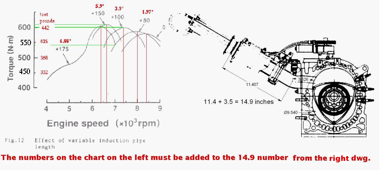
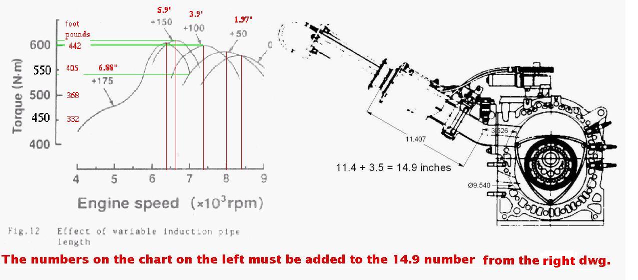
Based on our
experience, the diameter of runners determined rpm of maximum torque and
length of runners determined amount of torque at a particular rpm (torque
curve). And you can tell from the prior data, our power on the early small
port/plate engines usually peaked around 5500 rpm (that was our goal when we
started) and remained there through 6,000 rpm. Our earlier engines were
rated at 5500 rpm and the last engine at 6,000 rpm so you can see why the
increase in port and runner size. An important qualifier on any of our data
is that we were changing so much from engine-to-engine. For example we
changed injector locations in the trochoids many times on various engines.
I tried to get photos of most to document these but did not do as good a job
in this respect as I should have.
So we can't really document these precise
locations and various configurations accurately. Ditto port timing, sizes
and shapes. I know that unless somebody with the proper organization gene
helps me archive all our photographs/slides it probably won't happen. But
if we can do that it could possibly be a resource for some folks. We did
not do as good a job as we should have in recording and correlating the dyno
data to each change we made...and then finally reconciling that with flight
test data.
Most of that is my fault. We were doing a lot in different
areas and simply did keep good of records and comprehensive notes in the
file. We had a lot going on. I had to badger Everett constantly to make
dated notes for the file. And it was just Everett and me (with Francis Romig
our our master machinist in the shop) and we had to keep the other
businesses going concurrent with all the rotary work. I apologize the
record keeping is not what it should be.
Doug in Japan--per your note, we did not use EFI injectors for the direct
injection. We did work up a schematic of an electronic fuel injection system
that is still in the file from the late 1980's/early 90's. We had some
vendors look at it but never got around to building/testing. Don's modified
Airflow Performance-based mechanical fuel injection was so simple, provided
such a wide range of leaning in flight at various conditions and worked so
well we just stuck with it. A part of the reason was that when IMSA racing
was at its peak we were building twin-turbo Chevrolets for a customer who
was very competitive in that series and he wanted to try electronic fuel
injection.
The technology available to us back then was just evolving and
after all kinds of problems with vendors and quality control and technical
issues, gave up on it and went back to the old Hilborn lawn sprinkler system
with good results. We used some of those components to build the fuel
injection system on our first prototype SuperLight engine. From there we
went to Don Rivera's/Airflow Performance modified system which was much
better. The rotor housing injector locations we tested included placing one
and two injectors per rotor between the intake and exhaust ports in the
rotor housing. This dyno testing was done in November of 1991. Results were
disappointing compared to other injector locations. Power was down from 185
hp to 170 hp and BSFC to .74 from .54. And fuel flow for best power went
from 100 to 125.
We also tested injectors also in the plenum, intake
runners and a single nozzle angled downstream and shooting across the end of
the port at an angle from the exhaust side of the port. This latter
location seemed to allow more leaning and produced the lowest EGT. But in
flight testing we incured the WOT misfire noted earlier. This happend in
both takeoff and altitude in some instances. As noted in prior email, this
misfire was eliminated when we moved injectors to the intake runner just
where it enters the peripheral port. This produced the best combination of
power while eliminating the WOT misfire during the short period we tested it
prior to the crash.
Given the fact you are considering EFI direct-injection,
have you studied all the SAE wankel papers in this regard? Paul has some
good references. A good place to start are the papers by Charles Jones when
Curtiss Wright was going full-tilt boogie on the rotary (includes
multi-fuel); Bob Mount and Abraham after the project went from Curtiss
Wright to Deere/Rotary Power International; various NASA papers and work of
Kagawa, Okazaki, Somyo and Akagi at Mazda.
If you go forward with this, a
key lesson we learned from our dyno tests is that while essential, the
results don't necessarily translate to the same result in flight tests.
Part of this regarding the WOT misfure may have been that we did not have a
forced air induction for dyno tests. In this regard the one fundamental
thing that was gratifying to us regarding our work over the years with the
rotary aircraft engine project was that even though the little engine has
more BSFC challenges than a recip (high surface-to-volume ratio and trailing
quench after TDC), is has more potential for efficiencies in other areas and
these were clearly shown.
Through development and work on engine/airframe
integration, the combined in-flight efficiencies it offered allowed us to
fly the same mission as a recip on the same fuel burn. And there was a lot
of work in this regard we just did not ever get around to. Will try to do a
better job on the next one. It requires a lot of attention to all the
details in areas such as cooling drag. Paul's newsletter and his work of
helping educate folks in these areas is an invaluable resource in bringing
in new blood and advocates of the engine and furthering research. It seems
the challenges continue to be advances in BSFC and continuing work to
address reduction in noise and improving perceived sound quality without
sacrifices in efficiencies.
Paul, have you or others in the newsletter group read the work published
earlier regarding hydrogen and the rotary? Am sure the current work is
highly proprietary but would be very interesting.
Steve Beckham
------------------------------------------------------------------------
A lot of those early CW and JD papers were wishful thinking. RPI's final
papers came up with the same max BSFC as we are seeing with the
engine leaned to 150 F lean of peak. About .47. Since it is a rotating
combustion chamber engine the rich part of the mixture is being
thrown out towards the spark plugs.
I get the impression you guys missed this SAE paper.
You can download it from here.
http://www.rotaryeng.net/4-rotor-1-5.pdf
http://www.rotaryeng.net/4-rotor-6-11.pdf
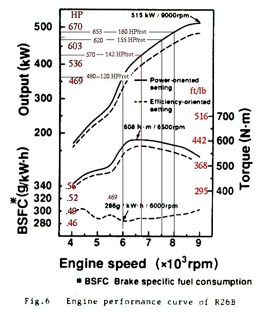
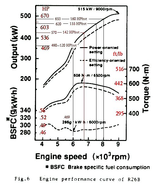
Therein lie the correct diameter and length of P-port engine
manifolds used at Lemans. This engine was generating 120 HP per rotor
at 6000 RPM. We verified this on the Mazdatrix dyno.
Of course we were also using our Teflon slide throttle design.
Yes I have the hydrogen papers and a lot of other stuff on hydrogen.
Hydrogen gives half the power and hardly any range :) Also kiss your trunk
space good bye. Since hydrogen takes more power to make than you get back
by burning it don't hold you breath on hydrogen. Pun intended :) Perhaps
if you are in countries that generate most of their juice by nuclear reactors
such as Japan and France it could be viable.
Paul Lamar ...No rotor no motor.
Steve,
On your 1 11/16 runner (42- 43mm) port and runner; what runner
length did you find gave the best hp performance at 6,000 rpm.
George ( down under)
The Rotary Engine NewsLetter. Powered by Linux.
ACRE NL web site.
http://www.rotaryeng.net
Copyright 1998-2007 All world wide rights reserved.