Paul,
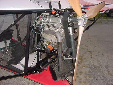
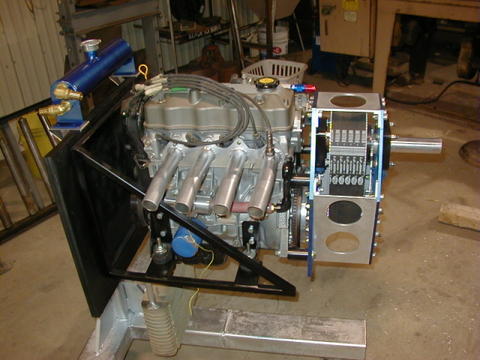
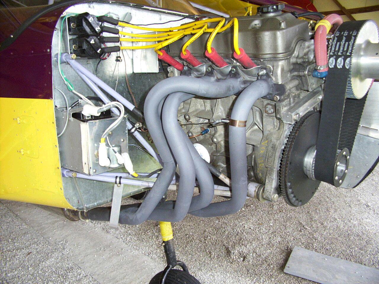
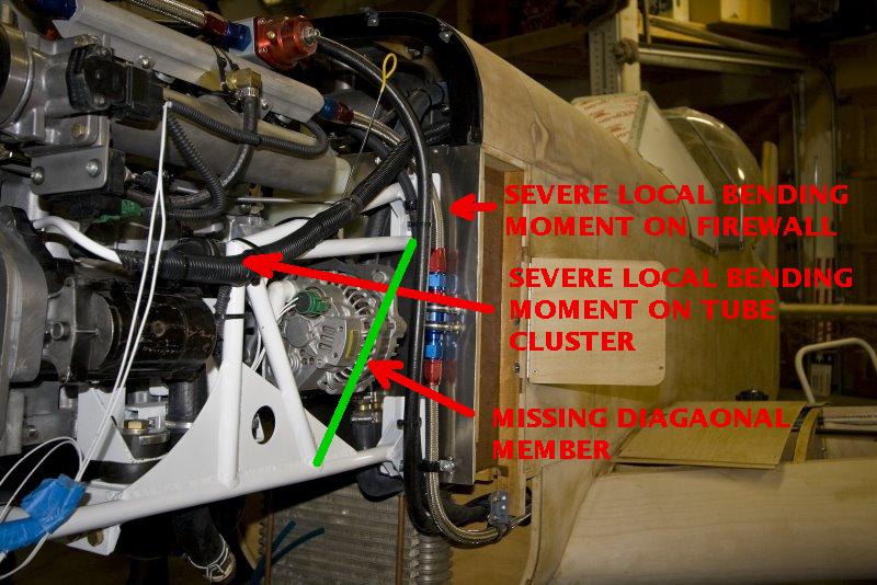
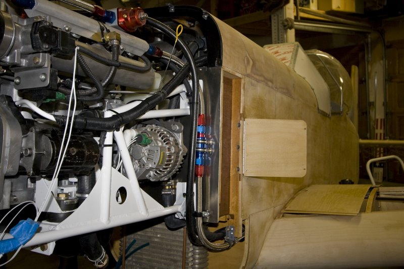
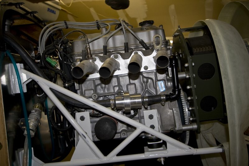
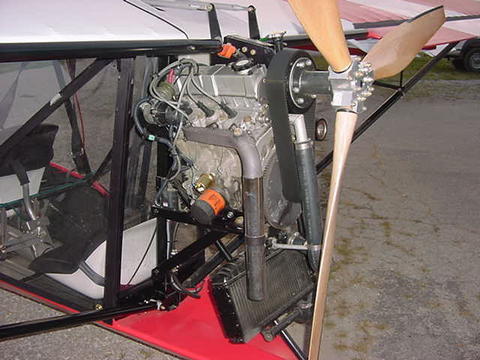
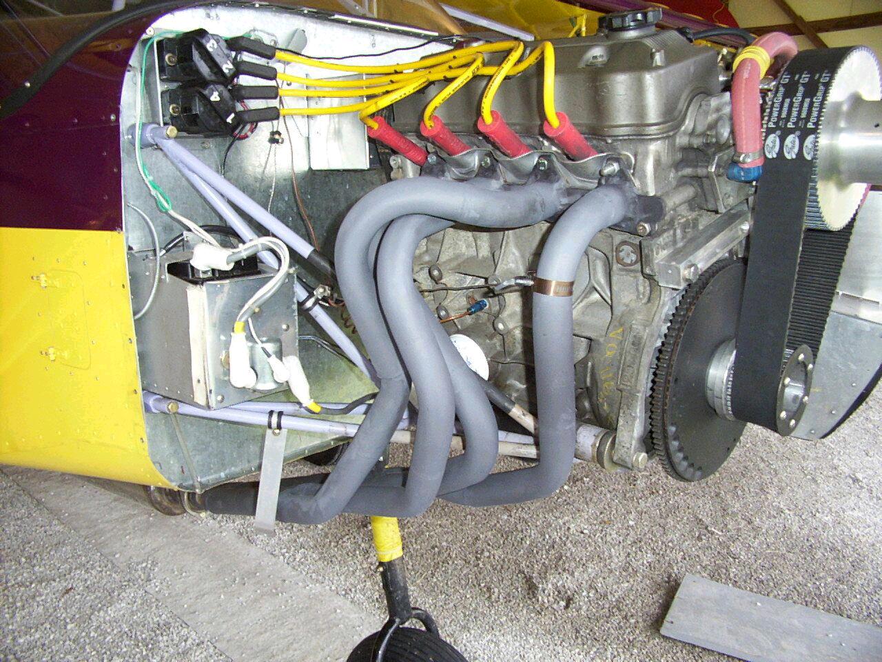
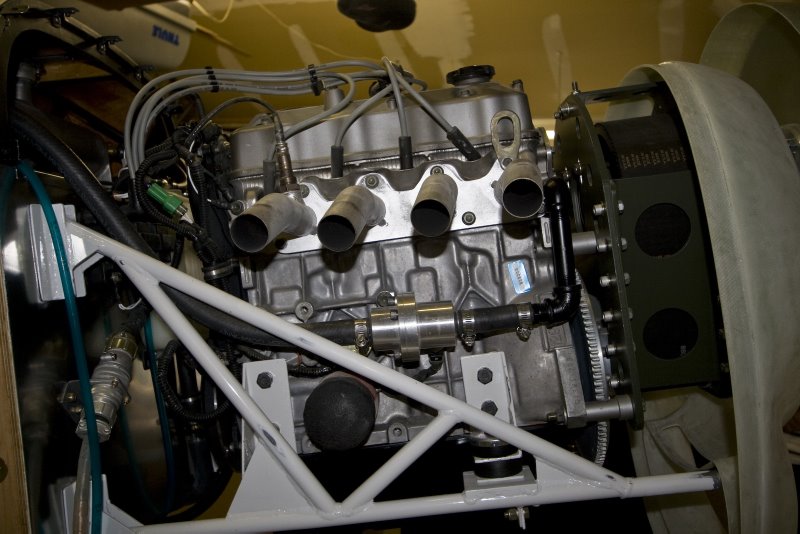
here are some photos of a local 5151 Mustang with a Suzuki/Geo engine.
The thing I noticed was that the engine mount didn't have any
triangulation. There is one piece of tubing connecting the right and
left sides of this mount, but I'm not real sure that the design is a
good one. The builder says that the engine is sufficient as a
cross-brace, but it is mounted with lord type mounts, and will allow a
bit of lateral movement. Would it be possible for you or someone with
more experience than me to do a structural analysis of this mount? I can
provide more detailed photos if you'd like.
http://picasaweb.google.com/john.marzulli/EAA1440ProjectVisitLoehle5151
Brian Trubee
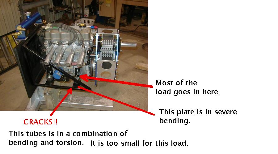
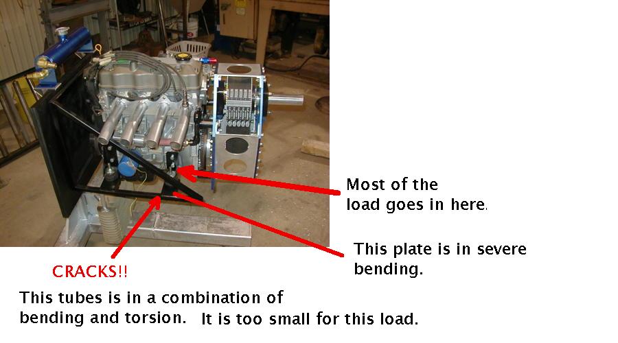
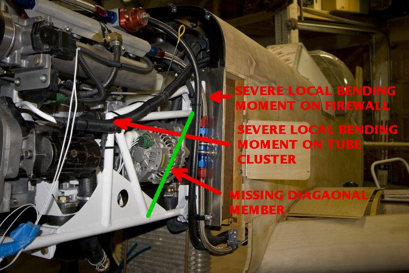
It is not just the lack of cross bracing.
Right up there with the worst motor mount designs I ever saw :)
You will need an FEA but I don't have that capability.
Paul Lamar ...No rotor no motor.
Actually, this looks like one of the more popular ("standard") mounts
for the Geo.
There is cross-bracing on the mount under the engine. Add 4 mounts and
it's pretty solid.
Part of the problem with the Geo mounts is that the engine lubrication
path assumes that the cylinders aren't vertical, so the engine is set at
an angle. You can see that in the pic of the right side. This makes
the mount look more kludgy that it really is, especially with the tubing
contortions needed to provide a way to get to the oil filter and
accessory pack for maintenance.
The real lesson here is that, FWF, reciprosaurs are nowhere near as
elegant as rotaries.
Keith Wood
------------------------------------------------------------
http://www.rotaryeng.net/motor.html
I could not disagree more Keith:)
>
> Paul Lamar
Disagree all you like. I'm telling you what I learned when I was active
in the Fly-Geo group (I was considering putting one in one of my
aircraft), before giving up that idea in favor of the rotary.
One of the major issues was engine mounts, due to the angle at which the
engine had to be mounted (as you might guess, dry-sumping was another
popular topic). In fact, the only topic which got more interest was
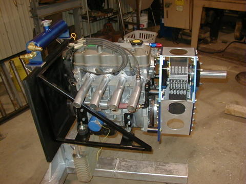
redrives (especially for the 3-cylinder model). Here are a couple of
other examples of the same basic mount from different aircraft.
Keith Wood
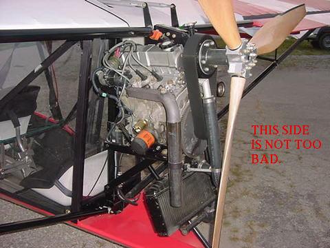
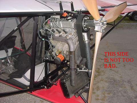
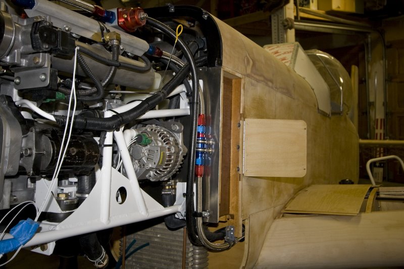
Well those are not quite so bad. Looks like you are talking about three
entirely different designs. The one with the white tubes is not too bad.
BTW the design can be really dumb if you want to make it heavy
enough. You can put the loads in the middle of a tube if it
is 2 inches in diameter and it has an .090" wall.
The Geo engine loads are about 1800 pounds on a hard landing
or pulling 6 G's in the air.
Ideal motor mounts are pure space frames. No structural members
of the frame are in torsion or bending.
BTW I just watched a video on the Corvette factory and the
writers incorrectly identified the Corvette chassis as a space frame.
I can't believe the Corvette engineers are dumb enough to call
it a space frame.
Many good books have been written on this subject.
One of the best is:
Analysis and Design of Flight Vehicle Structure by E.F. Bruhn
and others.
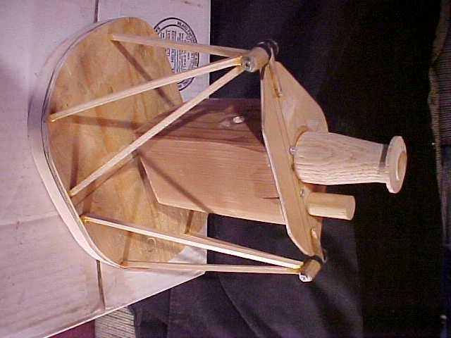
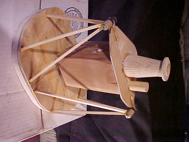
Also you will learn a lot if you make a quarter scale model
of your motor mount out of 3/16" square balsa sticks. 1/8th" diameter
welding rod also works. Apply some moderate loads and see
what bends and breaks first.
Paul Lamar ...No rotor no motor.
The Rotary Engine NewsLetter. Powered by Linux.
ACRE NL web site.
http://www.rotaryeng.net
Copyright 1998-2007 All world wide rights reserved.