A little background on our motor mounts for everyone:
Auto engines are designed to be installed in cars and not aircraft.
Unfortunately the Mazda rotary is no exception.
Aircraft engine designers gave some thought on how the engine was being
installed in aircraft so they provides certain mounting lugs for the
purpose.
These lugs are not found on auto engines. So we must come up with
something
else.
In effect what we are doing is copying the Questair Venture mount. If
it is good enough for a 500 pound, 600 HP engine and 350 MPH racer it is
good
enough for me. In effect their long Schertz beam located at the
engine/prop
CG is
a 2 inch diameter 4130 tube. Ours is a stronger 4130 rectangle .065 wall
3.44
inches wide and 2 inches high. 4130 has the best fatigue characteristics
of common aircraft materials. The long beam gives room for the exhaust
system mounted on the left side.
I was very impressed with Questair Venture MM structural design features
and its low weight to strength ratio. The designer choose not to use
the stock aircraft mounts for good reasons. In fact we use the same type
and
brand of Barry industrial rubber bushings. The QA engine is mounted with
only three mounts.
There is a course in structural engineering college called "redundant
constraint"
and load paths which has to do with why you only need 3 mounts.
People that have flown in QA's say they are one of the smoothest piston
engine
airplanes. The same guy that designed this mount also designed the piper
Malibu airplane.
You can read up more about motor mounts on
http://www.rotaryeng.net/motor.html
In the case of the Zenith 801 some of the loads go down that diagonal
angle
and into the side skin and back to where the landing gear is attached to
the
fuse.
The angles, with the fuse skins and the motor mount act as a beam. The fly
in the ointment
is the large hole for the door. All this is so complicated that only FEA
would
give a better picture.
In any monocoque structure most of the load is taken by the skin.
Wikipedia has a good dissertation on it.
http://en.wikipedia.org/wiki/Monocoque
The angles are mostly for stiffening the skin against buckling.
In our case the upper (mid) motor mount mainly puts the side and cowl skin
in
tension and shear and transfers some of the load back up to the tubes
going to the wing.
The upper (mid) mounts take about 800 pounds each horizontal load in a 6G
hard landing.
BTW the FAA standard is only 4.5 G's for landing loads. We design for 6
G's.
The prop torque load of about 600 foot pounds is about 300 pounds added to
one
rubber bushings and subtracted from the other due to the 2 foot OA lenght
of
the beam.
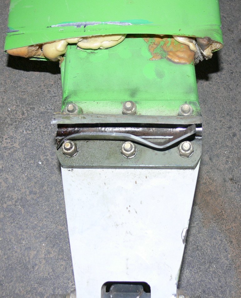
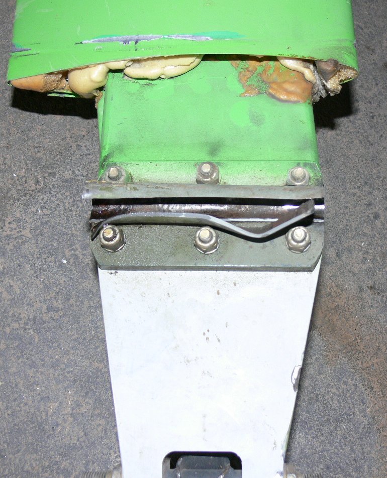
The load goes from the 4130 steel brackets (87F-11) into the lateral
beam (8F7-7) assisted by (8F7-1) and then into the skin assisted by the
angles
marked by red lines. It would be better if the mid mounts were moved out
board
closer to the skins. See Zenith firewall details jpg.
Of course if the mains hit first the aircraft pitches forward
and the nose gear then takes a lot of the landing loads. If it hits on the
nose gear first
it takes all the loads and the load path is directly into the engine by
way of the firewall and motor mount.
The thrust load never approaches those levels. Assume you have max climb
out
at 100 MPH or 150 FPS. Assume the fixed pitch climb prop is optimized for
100 MPH and reaches
max efficiency at that speed or about 80%. 250 HP is 137,500 pound feet
per
second
or 916 pounds potential max thrust at 150 FPS. 80% of that is 733 pounds
of
thrust total.
That is mainly applied to the mid mounts as each one sees half of that
or only about 366 pounds. At higher speeds the prop thrust drops of due to
speed.
You won't see max thrust and max load due to a hard landing at the same
time
so they are not additive. You probably have to drop it in from five to
ten
feet
or so to see 6 G's.
It would be easier to design these motor mounts if Zenith provided scale
dwg's of the firewall
with dimensions for most of the associated parts.
I am open to suggestions for improvements.
Paul Lamar ...No rotor no motor.
Doesn't the MM landing impact load depend on compliance of the landing
gear and tire system? Stiff gear and small tires might raise the MM
load for a given descent rate? Just picking nits..
Regards,
Matt-
True but we assume the 6G's are applied to the fuse to be
on the conservative side. It does not add that much weight to
the MM.
BTW I suspect the weak point in the load path is where the lateral beam
87F-7 is riveted to the diagonal angle. I would add a simple .035" thick
aluminum patch to the outside of the skin on both sides.
That would pick up the upper horizontal angles.
We ARE asking more from this A/C design using a 250 HP engine.
The original had, at max, a 180 HP 4 cyl A/C engine.
The rotary, at the 250 HP p-port level, is making as much
HP as a much heavier six cylinder A/C engine without the weight
penalty. As such it will make one spectacular STOL without
the fuel burn and cost penalty of a turbo prop engine.
--
Paul Lamar ...No rotor no motor.
Should be a neat airplane.
With your suggested beef up, where would you suspect the next failure
would occur? The reason I ask is that I'd like the next thing to fail
to be something cheap/easy to fix. I'm sure you're familiar with the
propensity of Cessna 182 firewalls (and 206) to get damaged without
doing anything bad to the motor mount or nose gear. Not optimum in my
opinion because the repair is laborious$...
One thing about the Bearhawk that impresses me is that Barrows
designed the landing gear to fail before the longerons get wrinkled.
While I think the Sherpa is a tremendously impressive airplane (in a
league of its own - deserving a 4-rotor p-port engine instead of the
boat anchor IO-720), I was disappointed to see that the the fuse will
likely get damaged before the gear fails...
Airframe parts should fail in the order of time/money required to
repair - absorbing energy in the process, protecting the expensive
stuff (me), ultimately.
Matt-
One thing I don't have Matt is 801 drawings with dimensions. I have no idea
how thick the skin is around the 801 nose for example.
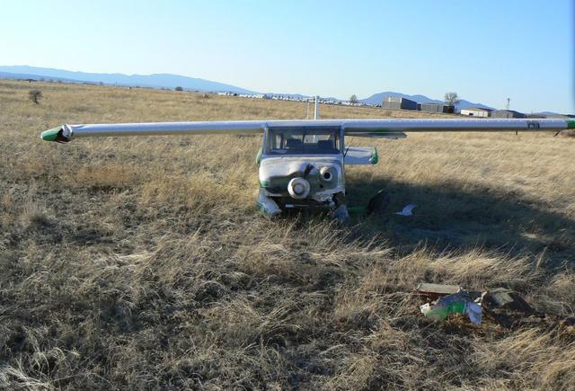
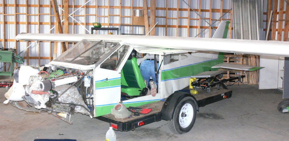
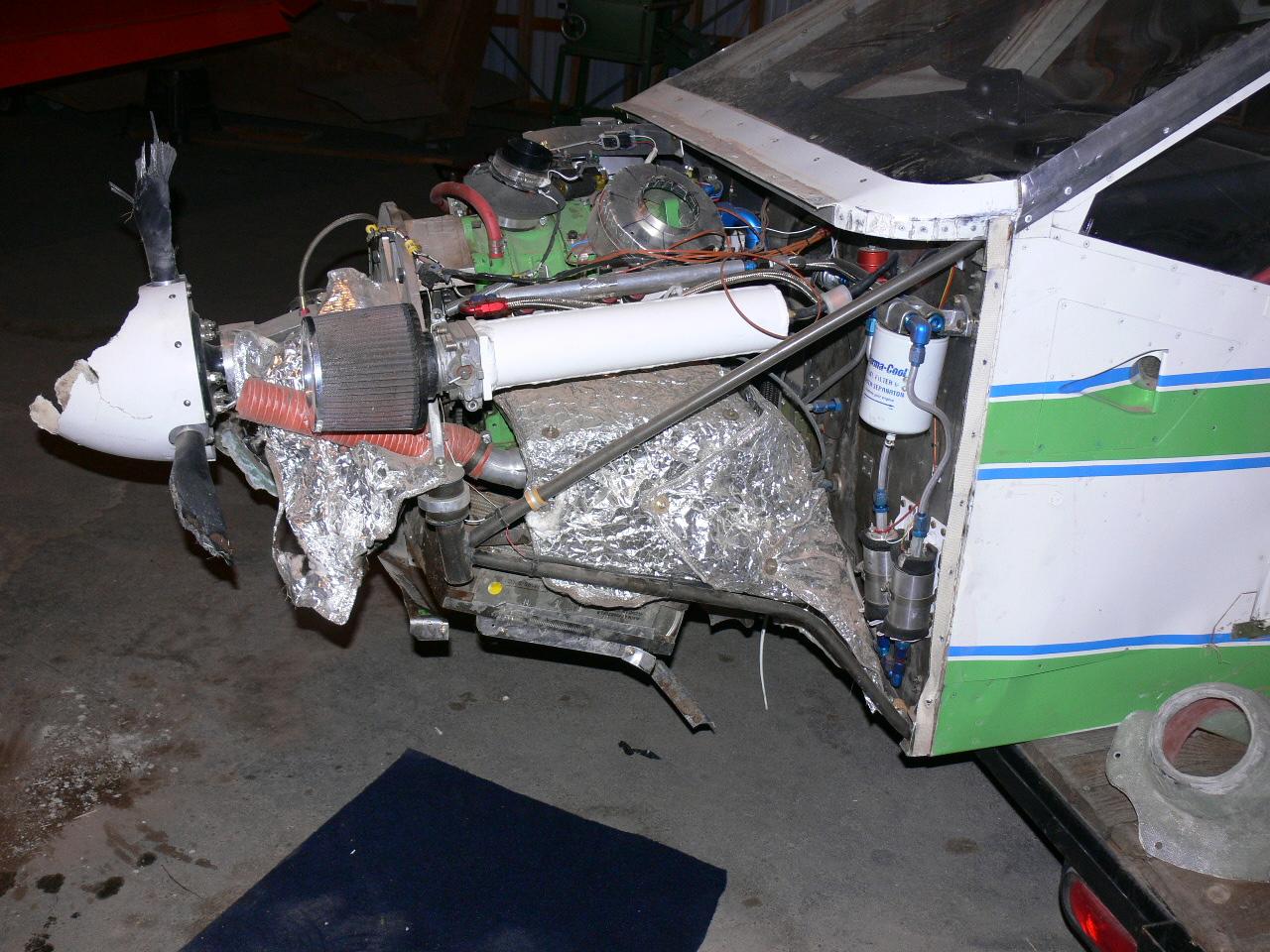
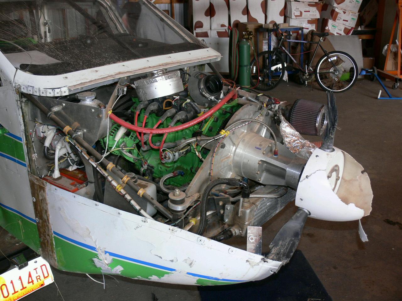
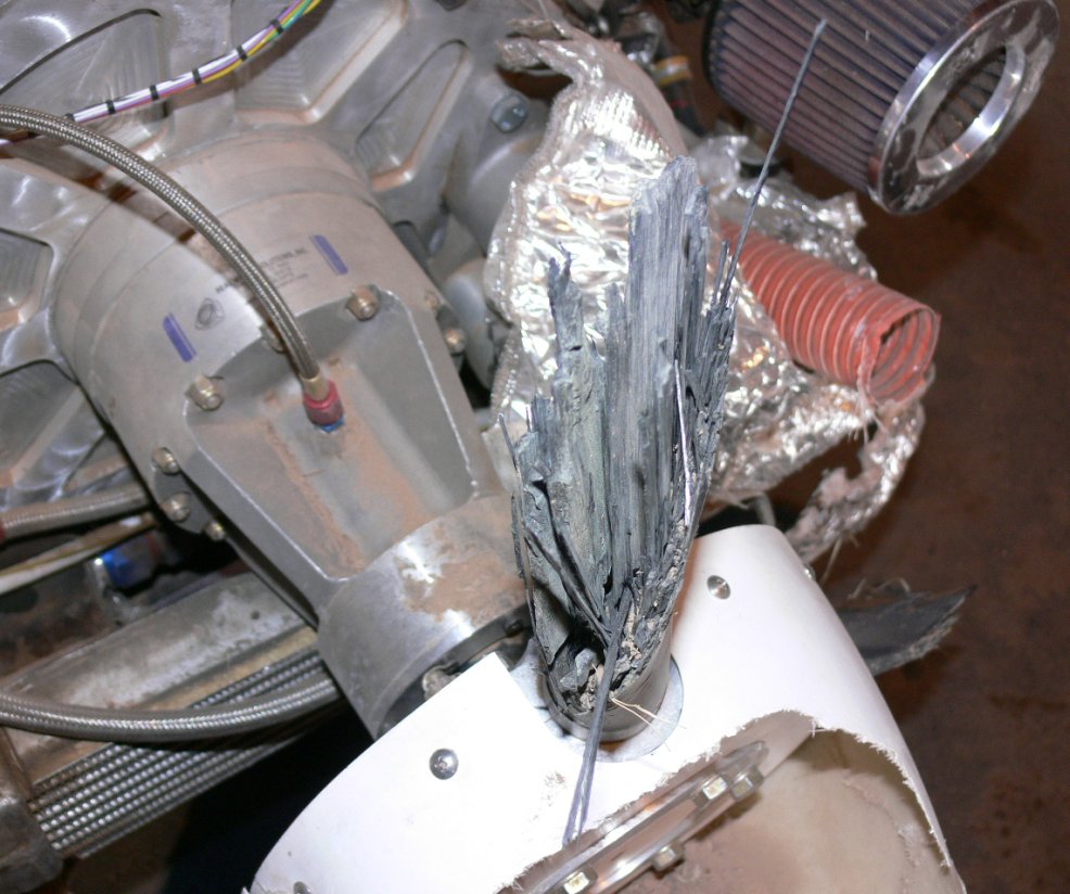
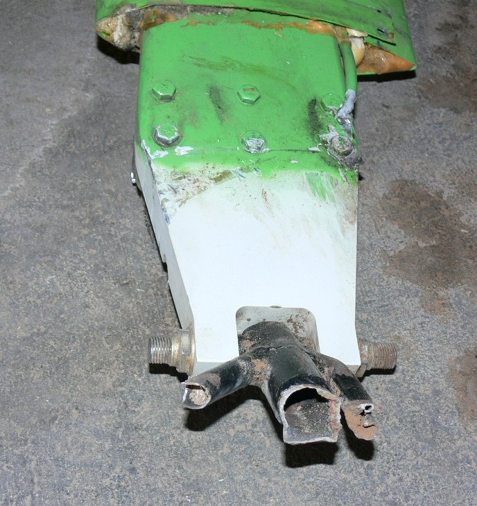
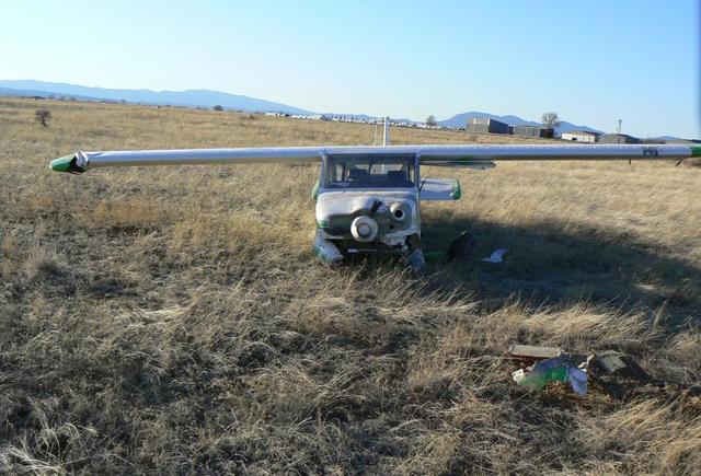
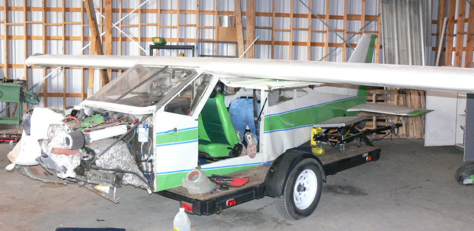
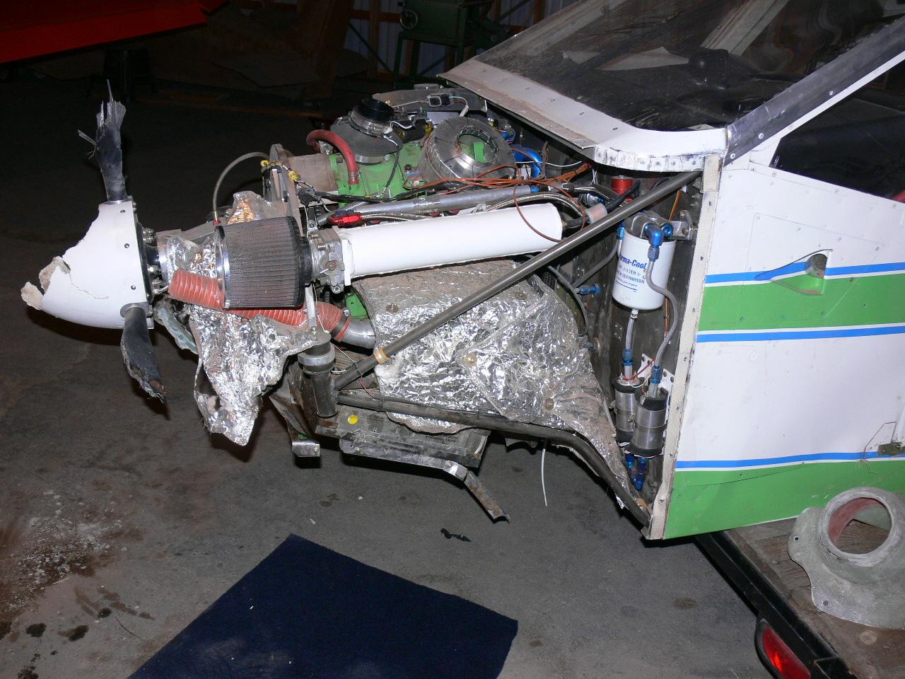
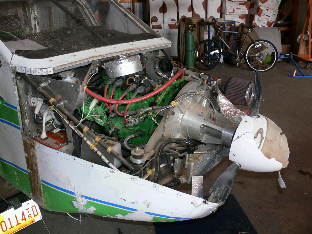
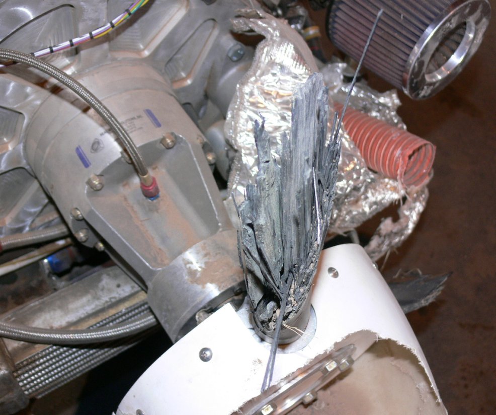
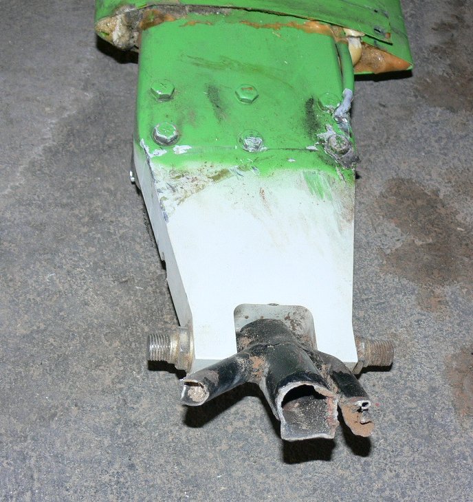
In Bob Whites BD4 crash the motor mount lower tube buckled as well as the aft fuselage
after the mains were wiped off. The rotary was running at near full power
and cleaned the blades off the prop hub.
It would be interesting to do an FEA for different crash scenarios.
--
Paul Lamar ...No rotor no motor.
The Rotary Engine NewsLetter. Powered by Linux.
ACRE NL web site.
http://www.rotaryeng.net
Youtube key word UTUBPLEASE
Copyright 1998-2008 All world wide rights reserved.