>>> Wouldn't it be wonderful if everybody developing an engine for use
>>> in aircraft could afford a dyno. It would be a lot safer if people
>>> tested their intended engine for horsepower on the ground instead of
>>> during the first flight. It would also verify or discredit some of
the
>>> claims made by vendors selling auto engines for aircraft use.
>>> All too frequently they claim xxx HP at 6500 RPM and then install
>>> a 1.4:1 PSRU.
>>>
>>> http://www.youtube.com/watch?v=sImSPvPglbI
>>>
>>> The History Channel had a well done video segment on HP so
>>> I incorporated some of that. They asked a bunch of people; "What
>>> is HP?" and few could answer. It is amazing how many people
>>> still do not understand HP.
>>>
>>> There are good pictures of Ken Welters rotary powered Coot and
>>> Power Sports rotary engine prop dyno.
>>>
>>>
>>> Please give it the highest rating as that encourages other people
to view
>>> the video. The more rotary powered cars out there the better. This
>>> insures
>>> a future
>>> supply of the rotary engines, that we all know and love, for use in
our
>>> aircraft.
>>> --
>>> Paul Lamar ...No rotor no motor.
Paul, your suggestion regarding dyno testing rotary aircraft engines
with reduction gear installed would be a major advance for flight safety.
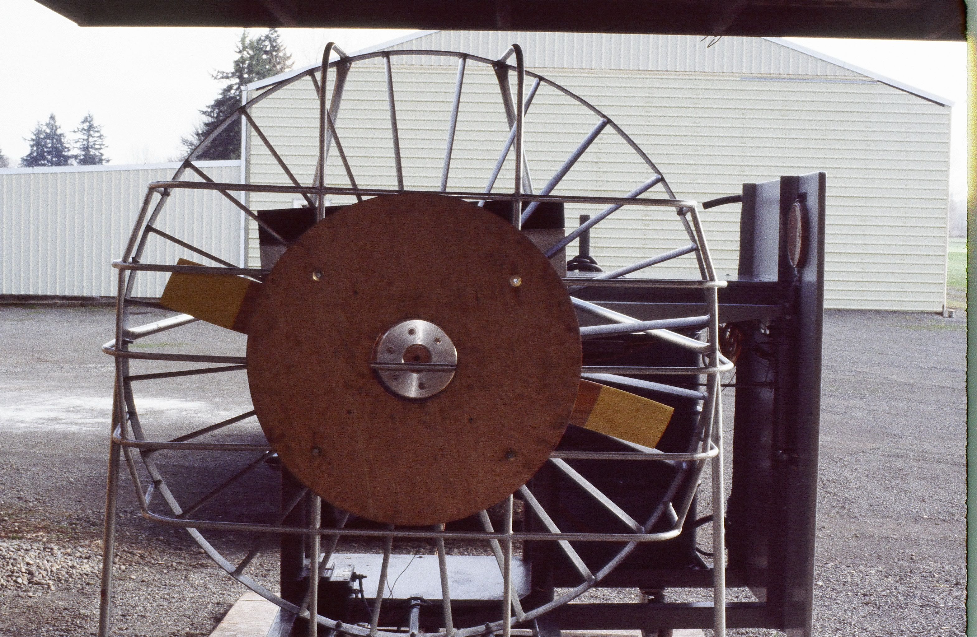
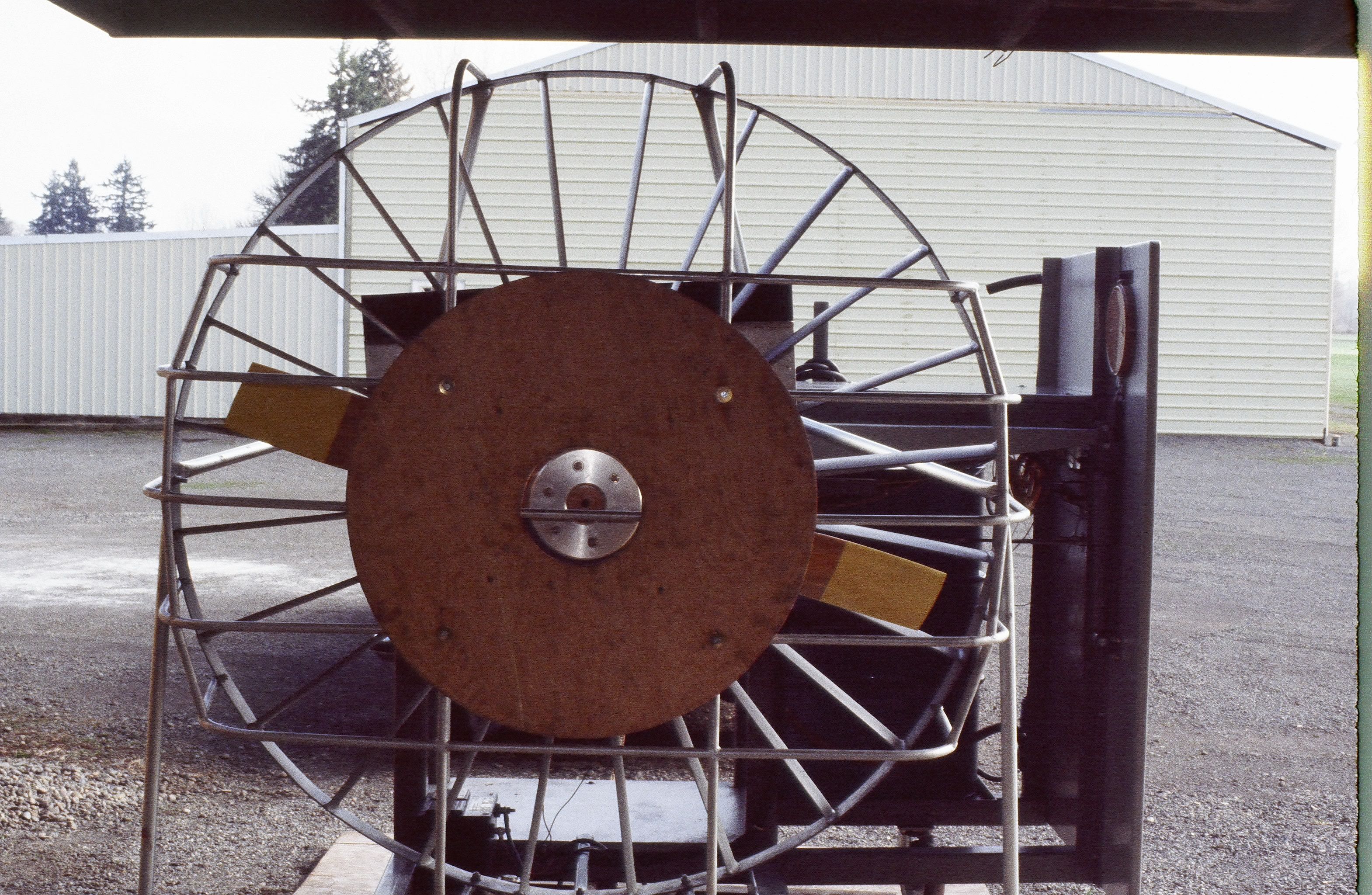
This is the dyno we built in 1990 to test both rotary and Lycoming
engines. Phillip Groelz and I earlier discussed providing it for a
free/cost only testing service when people have fully assembled their
rotary engines. Would you be interested in being the dyno master if we
did this so there would be a good consolidated data base regarding
component development, service issues, sound, and performance?
You may have seen the dyno when you were at the shop years ago. It
is basic and simple, using a torque arm connected to a rotary scale.
Uses the same principle as your drawing. We later added a pre-oiling
feature prior to startup. We discovered quickly that a shock absorber
for the torque arm was required for Lycomings due to the violent shaking
on startup/shutdown. For rotary engine testing, heat exchangers were
installed along the back on top in the prop blast.
The dyno instrumentation is old school so that would take two guys to do
power runs....one to run it and the other to log the numbers during
runs. Be good to have modern data acquisition if possible
cost-wise. That area is your expertise. Phillip talked to Rob Hickman,
the owner/designer of Advance Flight Systems who lives next door and
would work with us. His system records the data. We talked to Rob
earlier about doing one for the rotary RV-3 being built and considering
using it on the dyno to gather data. But if we were doing a lot of
engines we would want to have something dedicated to the dyno.
One of the major design considerations would be noise containment
provisions because the shop/hangar is at an airpark. An advantage is
that guys could fly in. We are about 7 miles from Van's Aircraft at
Aurora.
If we did this, seems as though we would want to use a variant of your
S-beam mounts to take just all 2 rotor engines. Would take a separate
mount for three rotor engines to put test club in proper location in
shroud.
---------------------------------------------------------------------------
Related background:
During the years we worked on the prototype rotary aircraft engines
using this dyno, it was stunning the number of things that broke during
testing before the engine ever got into flight tests. We learned a lot
about what would crack or break--exhaust pipes and mufflers, accessory
mounting brackets , throttle shafts, oiling issues, ,engine mount
tubes,drive belt harmonics and on and on. Granted the issues we faced
were greater because these early prototypes engines used many
original components and combinations.
Prior to constructing this dyno we ran the first Superlight rotary
aircraft engine in 1988 on the shop water brake dyno used for race car
and boat engines. Not good for the geared rotary engine because
without the propeller it did not provide the complete torsional
equation. Raised all kinds of hell with breaking input shafts,
reduction gear and pieces inside and outside the engine. The test
club shown here is the one we use for both Lycomings and rotary
engines. It started life as our first rotary engine propeller---84"
dia. and and high pitch. During early flight tests we lost a
stationary and internal rotor gear, and subsequently delaminated a tip
following the instant engine seizure. Cut down it maked a great test
club.
-----------------------------------------------------------------------------
Steve Beckham
Very interesting Steve. Thanks for sending that picture and background
info.
Yes I think it is the same one in the second picture here that I took in
your shop.
Your dyno inspired me to build mine.
Did you ever try it back to back with and without the stator?
Here at Santa Paula the sound is not an issue as we can tow our prop dyno
mounted on a trailer out to the far reaches of the field and it makes no
more noise than
a plane taking off. Also as long as you stay out of the plain of the prop
a safety
shroud is unnecessary. No more dangerous than running up an aircraft
engine before takeoff.
You guys were the pioneers. Now ten years later we have dozens of aircraft
flying with
many many hours using either the Ross gear box or Tracy's gear box with no
problems.
Some are using the latest six pinion Ford based auto tranny plantaries on
three rotor engines.
The secret is the torque pulse isolators.
Paul Lamar ...No rotor no motor.
Thanks Paul.
As to your points--
1. Running the dyno with and without the stator?
We ran the first engine on the dyno (a Lycoming) without the turning vane
assembly--had not built it and didn't know we needed it. But found the prop
blast exerted on the cylinders and evidently that long torque arm were
obviously skewing the torque readings significantly and as I remember a
significant improvement with cylinder cooling. Also the center blanking
plate(s) were used to adjust prop load/ rpm range for various engines--see
photo--using same test club. This included the engine we built for Dan
Denny's GlasAir III, a modified IO-540 . But if per your suggestion we can
make it work accurately without it, we should be able to test both 2, 3 or
even 4 rotor engines all with your same modified mount.
2. The note about noise is driven as much as exhaust and combined
exhaust/prop/gears. We found it necessary to do run, after run, after run.
Even with a muffler, the combined noise is a consideration in an airpark.
On engines tested before Mazda developed its port inserts, the noise without
mufflers was, as you can imagine, brutal. It was problematic even with the
low restriction mufflers we were using at the time. Neighbors for miles
would complain--and this was when we tested at the shop down on the farm.
But I think this issue can be addressed. We could possibly keep the dyno
down at the shop and test there but the logistics are a pain. And it would
be a disruption for Brent's operation there--he builds strictly automotive
and boats engines exception for some aircraft part component machining, and
balancing. And the airstrip has been allowed to deteriorate and closed.
3. Thanks for the photos of the rubber isolators. This is an approach
similar to what we tested for our earliest planetary reduction drive. On
subsequent planetary drive designs of various ratios using modified
automotive gearsets we moved away from rubber isolators because we were
shooting for something that would not be affected by heat, range of motion,
deterioration, cycling and ultimately were shooting for reduced parts count.
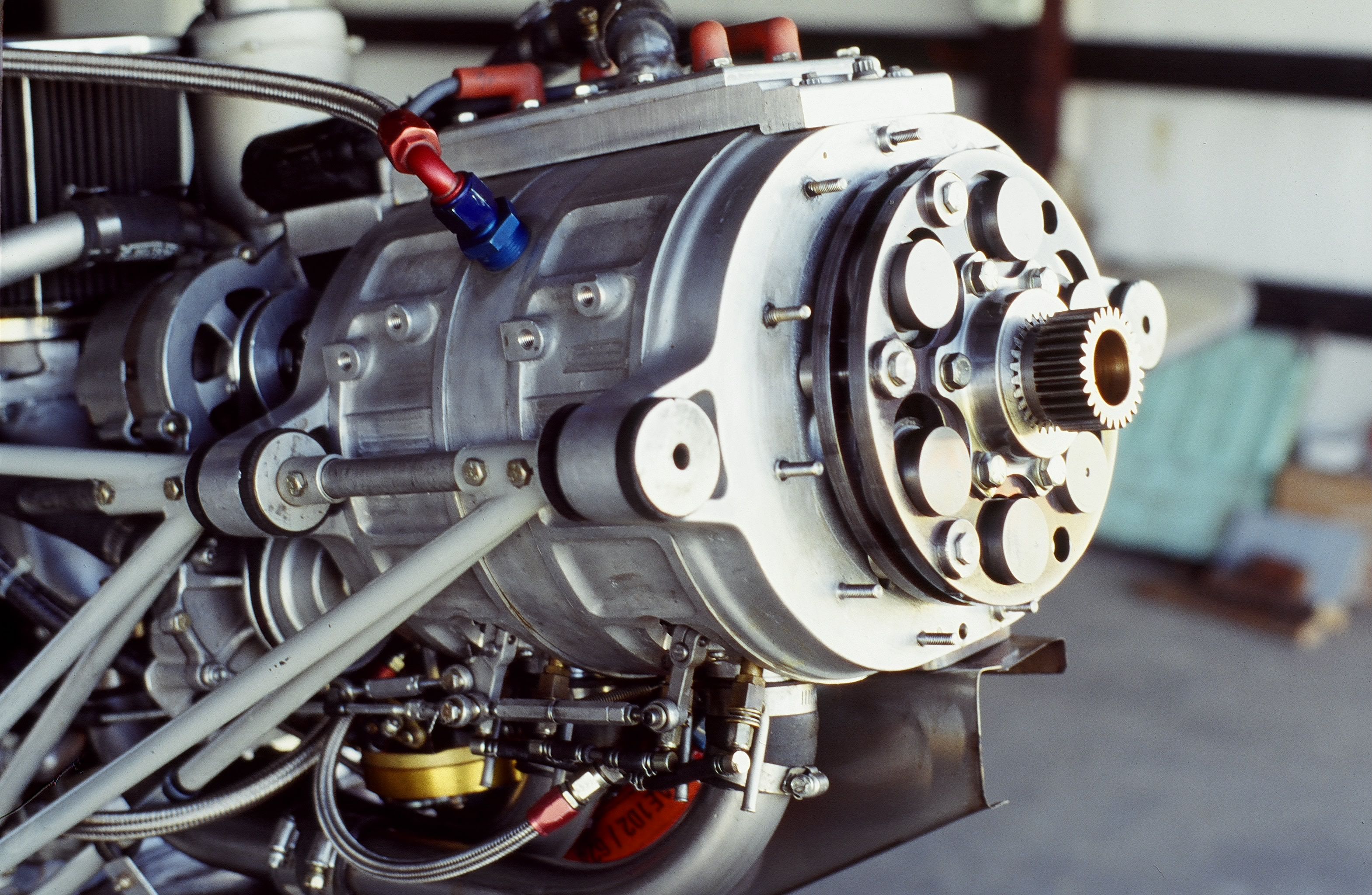
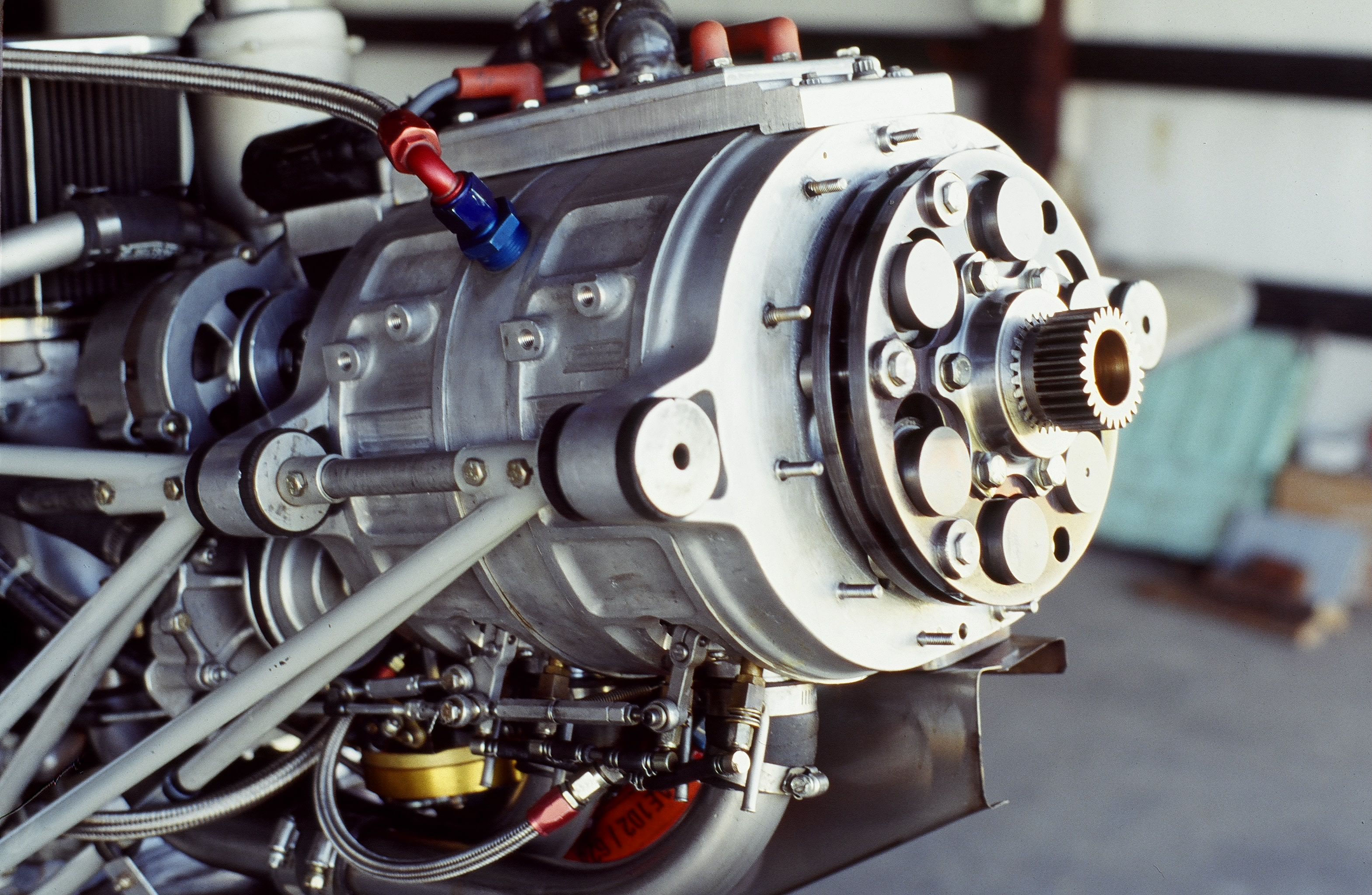
For gears, on the last SuperLight engine (see photo) we went away from the
Ford C-6 planetary-based parts used previously. On all the helical cut
planetary gears, we found end-thrust a limiting factor for sustained
high-output. Toasted end-thrust bearings. This problem was solved on the
last planetary we did that is shown attached by incorporating straight cut
planets produced by Allison for truck applications (2.08:1). And by then we
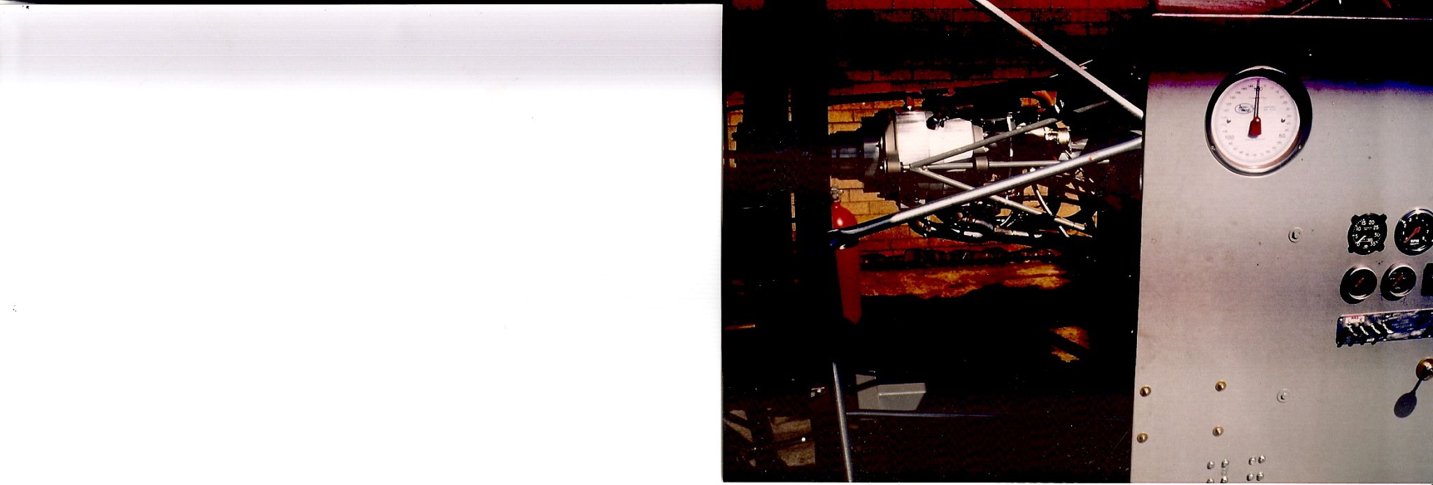
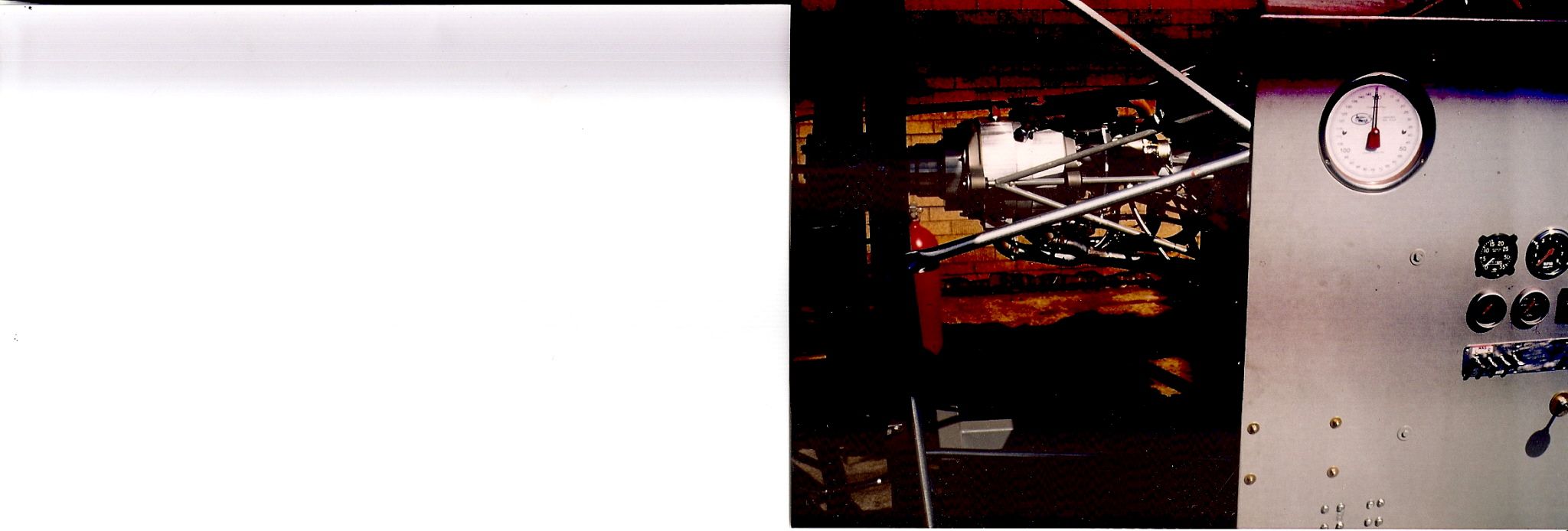
had fully sorted out our pendulous dampers shown in this photo. It took a
lot of design and fabrication work over two years but really did the job. A
photo of it on dyno attached. Apologize for lousy quality. It's scanned
off an old snapshop I took.
4.Ultimately we went away from the planetary reduction design because of our
decision to do the lower cost Iron Eagle Mazda conversion engine. To reduce
consumer costs the design goals included a simple, torsionally stiff gearset
without having to use any isolators, friction dampers, pendulous dampers or
anything and one that would hold up under repeated misfires....basically
using the propeller as the flywheel. That's why we went to an internal spur
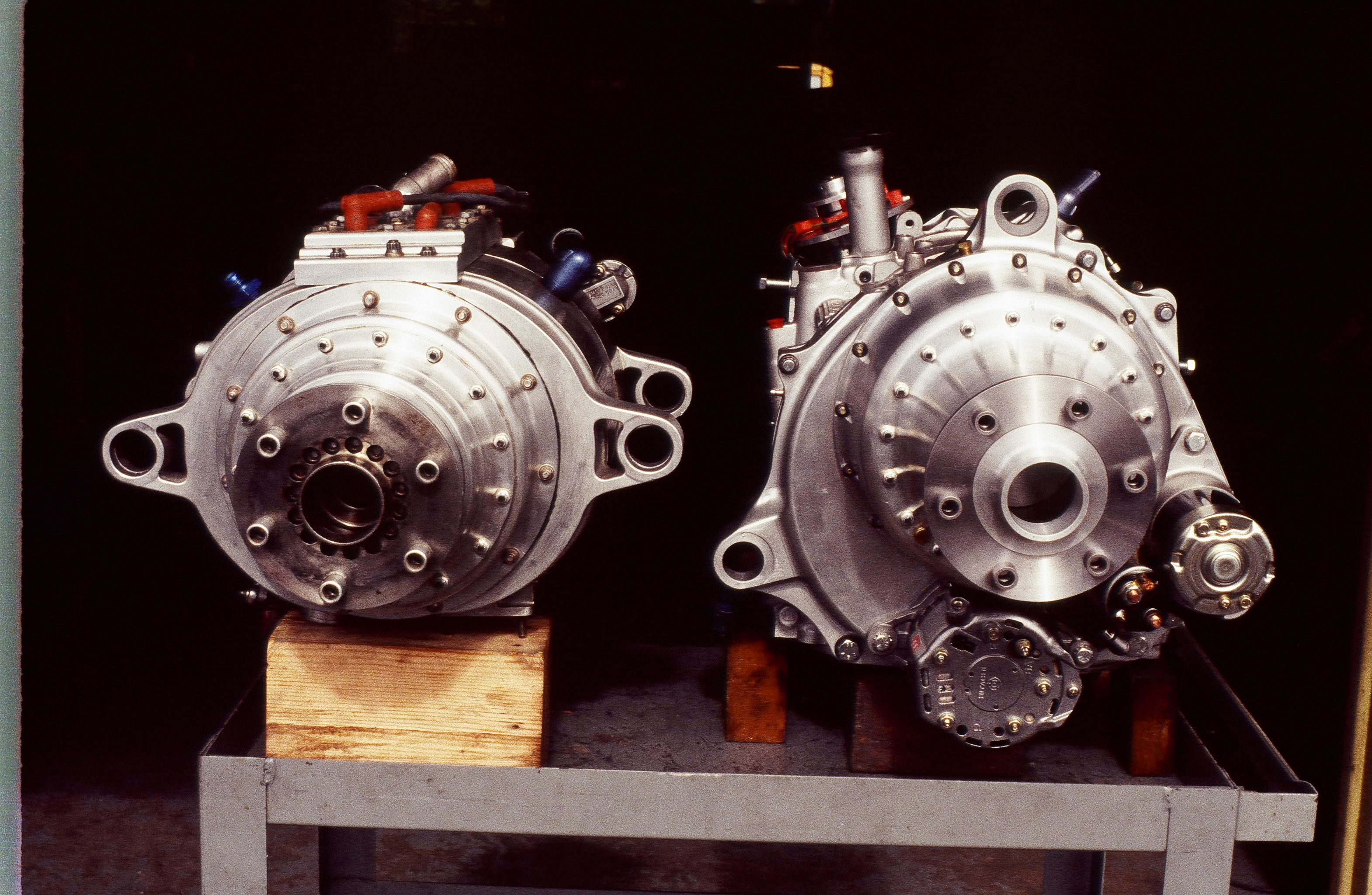
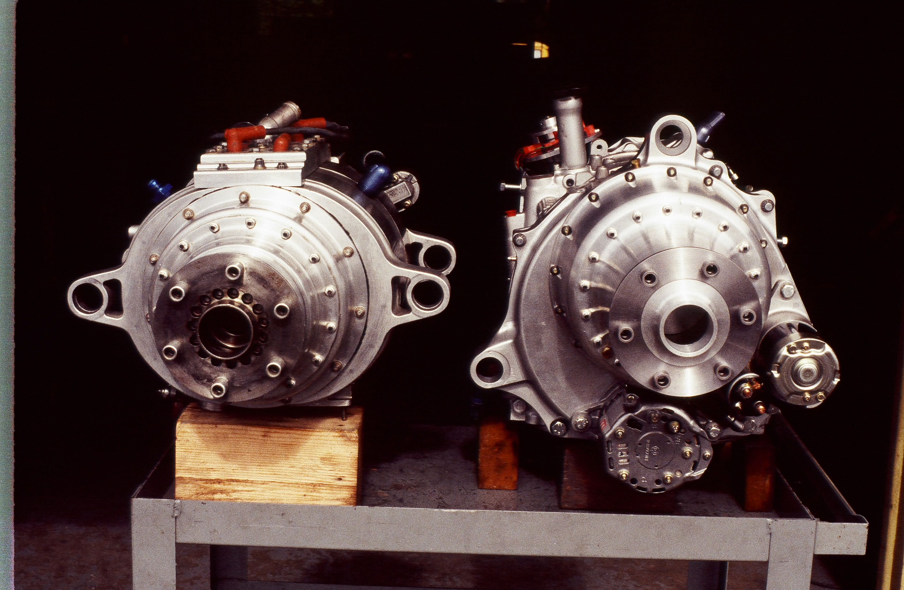
gear. The photo enclosed shows a view of the last SuperLight engine with
planetary reduction gear and the Iron Eagle with the internal spur reduction
gear. When I sold Powersport it was with the desire that this SuperLight
engine be donated to the EAA Museum. Hopfully it was not cannibalized for
parts. It was a neat piece and incorporated interesting stuff not known to
folks. It represented about 10 years of work. With the sale they also
received our direct-drive, furnace brazed lightweight steel engine not yet
run.
5. Hope to see you at Marysville but it appears weather may be an issue up
here for mountains unless launch today.
Steve Beckham
The Rotary Engine NewsLetter. Powered by Linux.
ACRE NL web site.
http://www.rotaryeng.net
Youtube key word UTUBPLEASE
Copyright 1998-2008 All world wide rights reserved.