>>>
OK Steve a couple of questions if you would respond. I can't quite get
my
head around what you said about the exhaust manifold. I know someone
used
4
studs instead of the two standard studs, but the material in that area
seems
a bit on the light side. I thought perhaps a standard flange with 4
threaded holes or studs to accept a 4 hole header flange might be a
better
option. This would be a flange on a flange - again more weight.
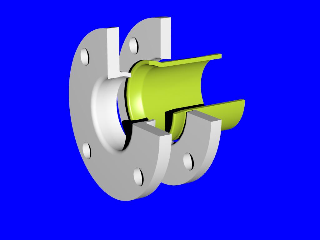
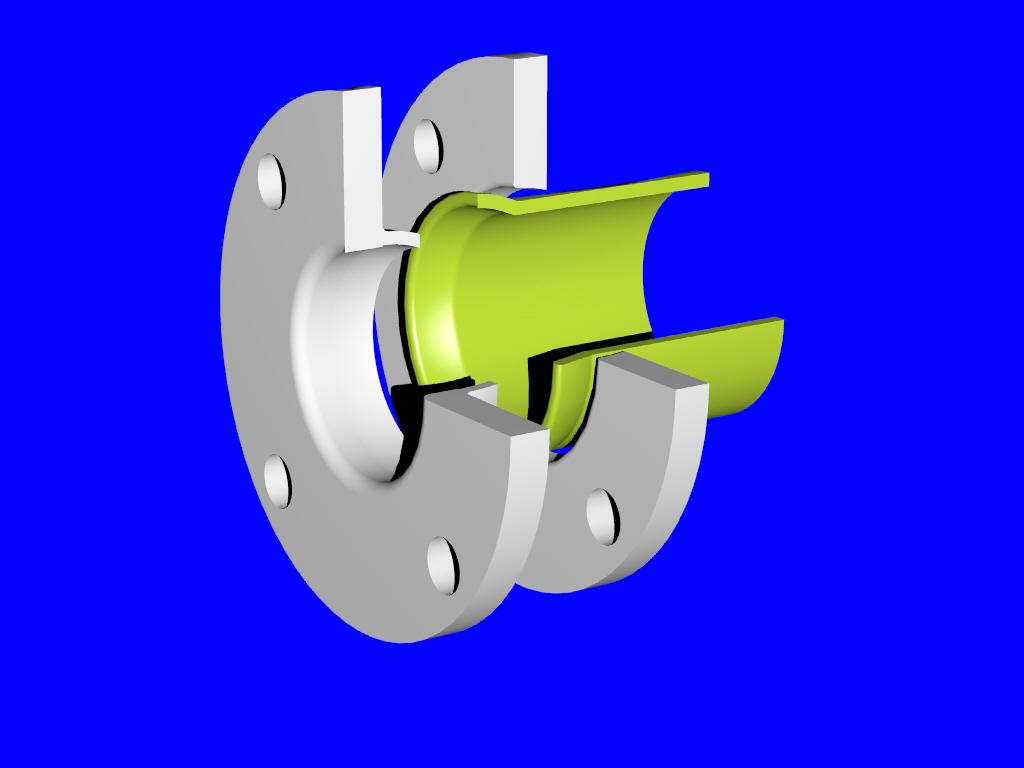
On the attached drawings [Solid-Works???]which are a collaboration
between
myself and Bill
Jepson, I have tried to show the cool air flow.
I take on board your comments on drag, but safety are a greater concern
for
my application and cooling the exhaust will extend the life of the
muffler - also this could be consider a mixer and a lighter muffler
used
down stream and again the cooling air would make this feasible IMHO.
This
would then be a very quiet set-up.
The most important part of this design is the deflectors, which was
Bill's
idea. To deflect the sonic waves, which scrub around the inner can
turning
into the sound into heat. The part of the design which was mine was how
to
hold them in position, so I came up with the cool tube - which served
two
purposes.
The rest of the design revolved around what off the shelf cones I could
get
hold of. I think it came together nicely - now only if it will work, I'm
pretty sure it will.
321 would be nice, but Inconel is too expensive for this poor man's
exhaust,
so I used 1.6 mm- 316SS which is an industry standard in a lot of cones
available. I'm now glad I did use the 1.6mm material.
I'm pretty sure you could get the cost of material down if you have the
contacts but that's the best I could do at that point in time.
I had a contact in the Aviation exhaust manufacture and the manufacture
everything from 321 SS plate but I was looking at $1,000 min. Not an
option
for my application. I know it's cheap for the racing guys but I don't
have
sponsors.
George ( down under)
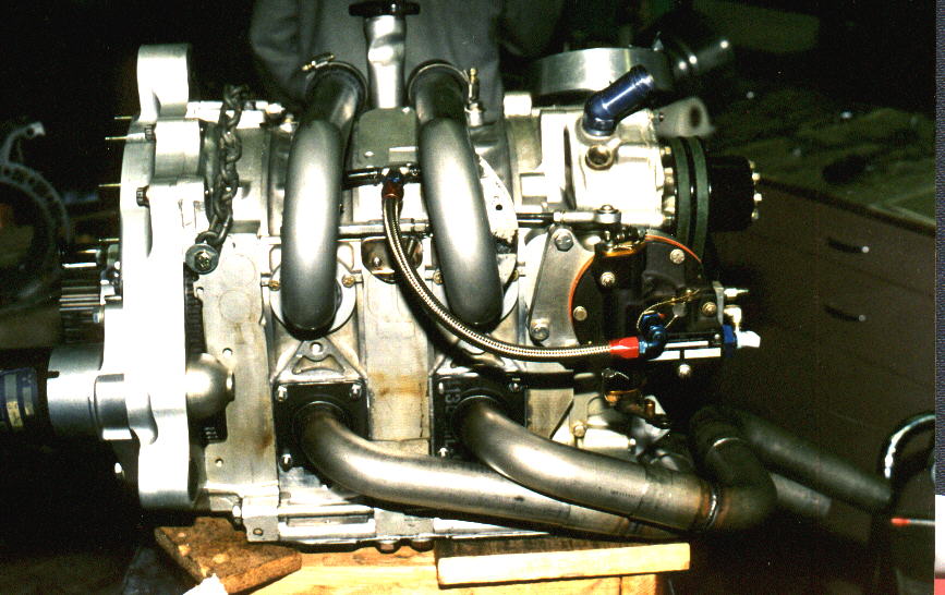
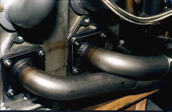
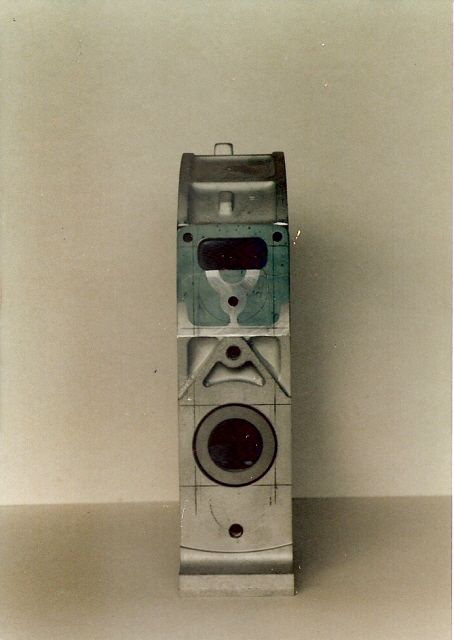
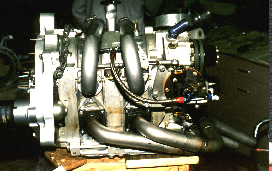
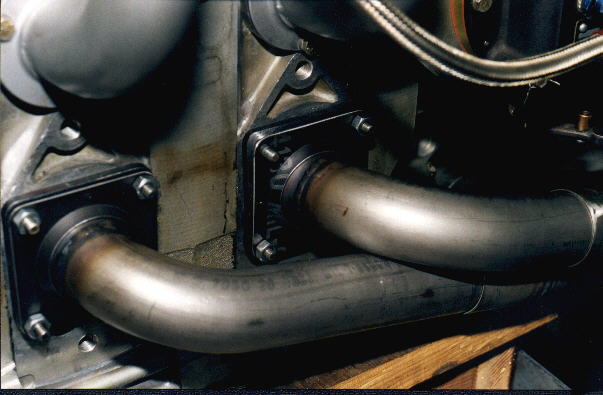
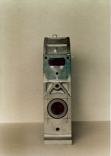
George--regarding your question, we used no exhaust manifold after the
first
prototype engine, just four-stud exhaust flanges. Here is a scan of an
old
photo showing stud location beginning in the late 1980's and for all
subsequent engines. Minimum spacing was 2 1/4" and maximum spacing used
was
2 3/8". Have not lately measured the newer rotor housing castings to the
older ones, but don't remember that late 80's to present 13B castings
were
substantively changed dimensionally in this area. We never had a problem
using this approach. If you try this, just don't go crazy putting too
much
torque on nuts. Studs were installed finger tight only, with never-seize
applied lightly on threads in rotor housing and on stud threads. Flange
thickness used was from 3/16" to 1/4". Flanges were surfaced nice and
flat
after welding and no gaskets used; high temp silicone only. This
installed
configuration is shown on Paul's photos of the system installed on the
engine.
Steve Beckham
Probably part of the reason the apparent minimal sealing tech works in
this location is that it's against the rotor housing which is water
cooled aluminum.
Slip joints work great except for turbocharged applications(?).
Matt
Matt--yes, we transitioned to slip joints exclusively except for the later
style ball joint at the port on last engine. Slip joints were simple, cheap
and worked great. After transitioning away from an exhaust manifold, on
second system we welded simple little stub stacks no more than an inch long
to the exhaust flange then a slip joint over that with exhaust pipe and
good quality stainless safety wire to tabs each side for retention. Worked
great but looked a little cheesy and did not address movement about the axis
of the engine centerline. But we simply isolated the entire system near off
the engine mount or fuselage with thin steel strapping held to exhaust with
stainless clamps, then rubber isolators each side of the strapping where it
attached to engine mount or fuselage. The thin spring steel strap was bent
like an upside down "u" with the sides angled out and horizonal legs where
the clamps went. The spring steel allowed movement and kept heat away from
the isolators. From that system we later went to the more robust all-axis
port ball joints which Paul has shown. A lot tricker but a lot more work
also.
Steve Beckham
Somebody should off these things as a kit. Beats the Racing Beat flange
on weight alone not to mention the tube welding on the outside problem.
Paul Lamar
The Rotary Engine NewsLetter. Powered by Linux.
ACRE NL web site.
http://www.rotaryeng.net
Youtube key word UTUBPLEASE
Copyright 1998-2008 All world wide rights reserved.