Paul,
You have often mentioned the gains in horsepower that can be had by
having a big rammed air scoop on top or side of the cowl compared to an
usual inlets next to the spinner.
I am trying to design size such a scoop now to trade airspeed for
horsepower.
As you know in trying to dedicate the exhaust turbine solely for turbo
compound use, I am stuck with a supercharger for boost. The Rotrex is
efficient but to carry three psi of sea level boost at altitudes above
15K it is going to cost me at least 20 to 25 engine hp. My goal is to
reduce this by one half at least.
For all you guys thinking electric supercharger, stop and do the
calculations. I did. Hint.. HUGE amperage, thick heavy cables even at
24 volts and lack of sufficient wing area for PV panels. Did I mention
weight? Ok back to reality. Lets say the scoop is sized at 40 square
inches and allowing for skin drag losses then the supercharger
compressor sees a little more than 5 times the pressure it normally
would without ram effects. Nice. Note at lower altitudes I have enough
boost to not engage the supercharger. At high altitudes if I want the
power, turbo compound and advantages of the jet streams, then the engine
or plane is going to have to work for its lunch.
My assumption is that if I oversize the compressor and make sure it can
handle the volume, then it will work less, and I can run it at its 80%
efficient sweet spot.
For my study I:ve selected model number 30-94. It has a maximum boost
ratio of 2.7 if needed. It is normally used to boost engines wanting
from 250 to 400hp.
The maximum flow is 0.37 kg/sec or 48.84 lbs/min.
So again I am trading airspeed (drag) for work but I suspect the
merits of compressing air and gains in HP. are going to outweigh the
drag of my plane at 140 knots. Especially if the exhaust is designed
well.
Givens:
My chosen airspeed is 140 knots.
The opening to the Rotrex compressor is 76mm or 7 sq. inches.
The P-ported 13B engine is running at 6000 rpms.
At a density altitude of 18K` the STP ambient pressure is 14.95 inches of
Hg or one half that of sea level. In psi terms that is about 7.5psi.
I then need 7.5psi plus the additional 3 psi or 10.5 psi. total of boost
at 18K altitude to equal what the engine would do at sealevel.
The STP temp there is minus 5.14 degrees F. which is good for compressing
air and allows the engine to run cooler. Bad for heat exchanger as the
density is less. Oversize the heat exchangers.
The intake scoop again is 40 square inches ( about 4x10 inches)
Engine air flow needs are estimated as follows:
My rough guess. running E-90 at lean A/F of 14:1 and 0.46 BSFC (probably
more) and 220 hp.
220hp. x 0.46 = 101.2 lbs. of fuel per hour. Divide by 6.4 lbs/gal
(ethanol is heavier) = 15.8 gal./hr. Weight of air is 101.2 lbs x 14
equal to 1416.8 lbs/air per hour and 23.6 lbs per min.
Note* Piston engines produce about 120 hp per 0.1kg/sec of air or 13.2
lbs per min. on gasoline at stoimetric. Double it and you can see my
above calculation are close as gasoline and E-90 have different A/F
ratios.
I need help calculating what pressures and air flows the inlet of the
compressor actually sees. I believe pressure quadruple as speed
squares. I imagine the calculation is done in terms of plane velocity
stated in inches per minutes times the frontal area of the scoop. This
gives cubic inches per minute passing through the opening and we know
how many cubic inches are in a lb of air right? But how many psi of
boost are we picking up at this altitude and speed? One fifth the
volume weight?
I know this is your expertise Paul and I would appreciate any advise on
how to do the proper calculations when you have time. No rush.
Thanks
Doug in Japan.
The intake scoop in theory sees dynamic pressure but that is not what you
will measure in the intake duct as the engine is sucking air through the duct.
What you see at the compressor face will also be a function of how smooth and
how large the scoop area is which you just pointed out.
When the flow into the duct is equal to the forward velocity of the airplane
the drag coef. of a boundary layer bypass type scoop is about .2 based on the frontal
area of the scoop and according to Horner's data. It goes up to .4 if there is little
or no air going in. Surprisingly it also rises ever so slightly when more air is
being pumped in than would be indicated by the forward velocity of the aircraft.
If the scoop is in the slip stream of the prop there will be a mild supercharging
effect. I would add 20% to the air stream velocity at take off and low angle
climb out. 30% for high angle climb out. Much more for static of course. The static
slipstream speed could be as much as 100 MPH. Pito tube dynamic pressure data in that
area would help enormously during development. This type of scoop should help greatly
on getting on the step and out of the water.
BTW dynamic pressure is .0026 times MPH squared. The .0026 is air density
related to MPH.
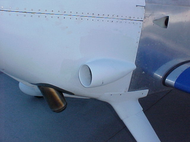
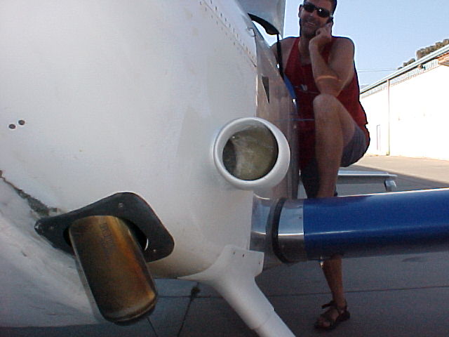
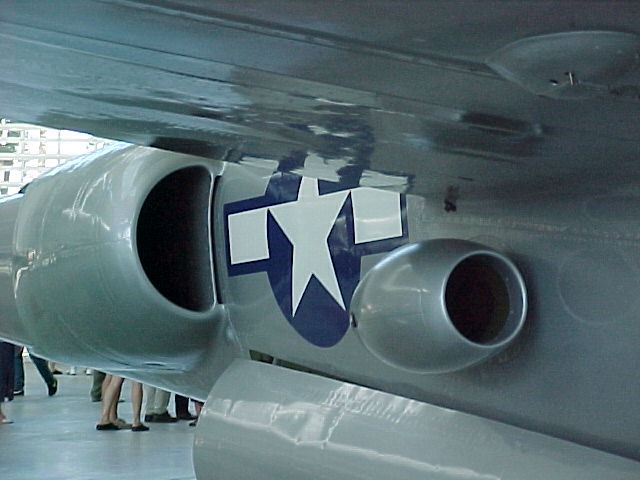
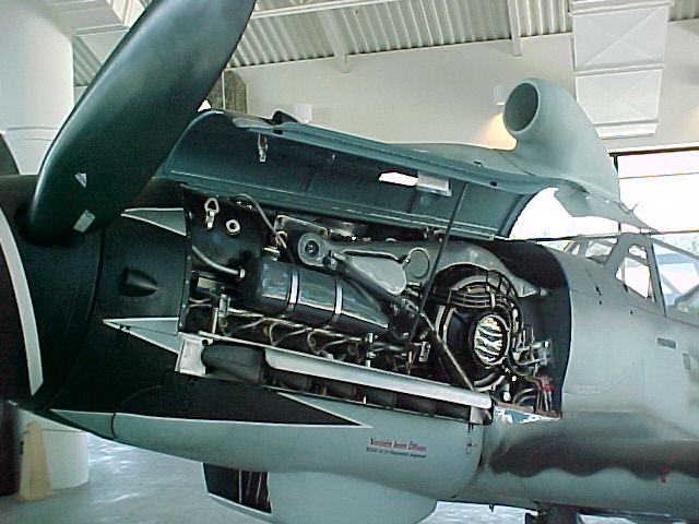
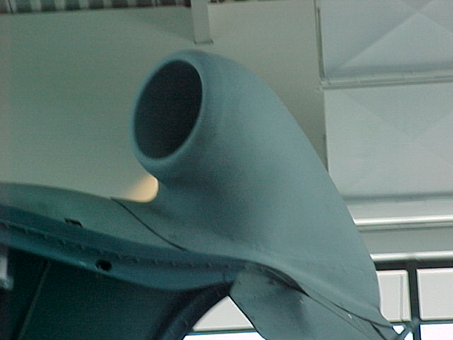
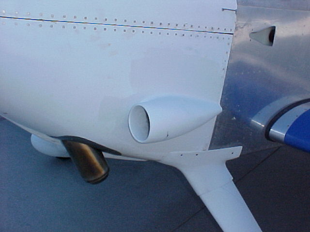
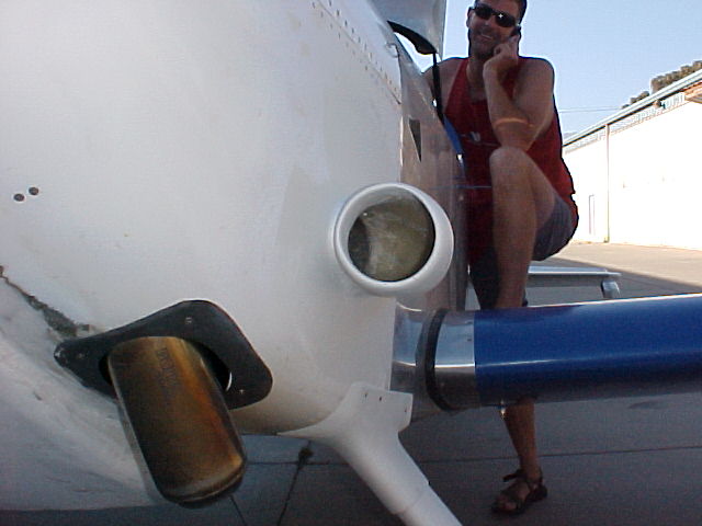
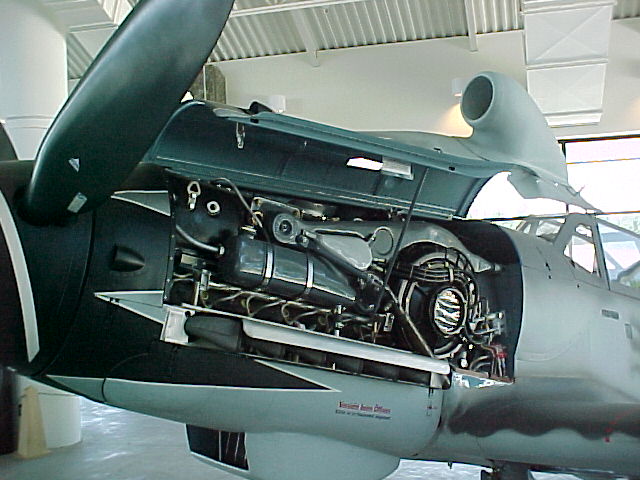
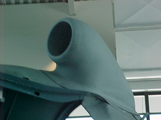
Here are some pictures of Dave Leonards scoop and others so the new people know
what we are discussing.
--
Paul Lamar ...No rotor no motor.
The Rotary Engine NewsLetter. Powered by Linux.
ACRE NL web site.
http://www.rotaryeng.net
Youtube key word UTUBPLEASE
Copyright 1998-2008 All world wide rights reserved.