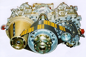
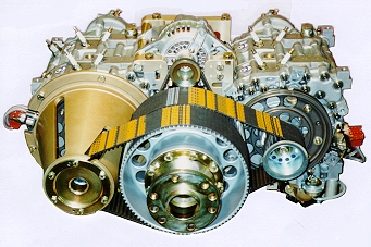
I think it's likely possible to weld the e-shafts
together to
eliminate the necked-down section (and obvious
stress riser there).
There's plenty of material to work with to get a
good weld. Is there
room in the housing to add a (nicely radius'ed)
doubler coupling - to
build strength at the joint (probably not needed)? At least for
non-boosted applications.
There are lots of automotive stroker cranks that are
welded to extend
the throws (though the best strokers obviously use
custom castings or
forgings).
The downside I see is that the alignment through the
engine (between
the two 13b's) may become somewhat more critical now
that there
wouldn't be any movement allowed by the (now
missing) joint. Dowel
the sections together?
It would be fairly cheap to try. I don't get the
impression e-shafts
are hard to come by..
Matt-
I don't think welding will work either. The shafts
diameters were designed
for a two rotor. I am amazed that people don't have
trouble with the 3 rotor
e-shaft. The Le Mans four rotor never ran more than
24 hours at full power.
ANYTHING will work if you limit the HP and or for a
short period of time.
Four rotor e-shafts are kind of easy to make
comparatively speaking. Why ask for
all the problems of two..... two rotors coupled
together?
--
Paul Lamar ...No rotor no motor.
paul,
he says on the second page that he made the coupler by
welding both shafts to build them up. i don't know how
sturdy it is though, but he claims it worked.
gary in midland
----------------------------------------------------
Quote.
The front eccentric shaft...
The rear section beyond the rear main bearing area
must have material added so that the front half of the
coupling can be machined into it. We mounted the shaft
in a lathe, and added the material using a MIG welder
w/ standard steel wire. Add enough material to the
former flywheel mounting section to maintain the full
1.690" diameter of the rear main bearing journal for a
total length of 3.050" from the face of the rear rotor
journal. After everything slowly cools off, the added
material can be machined to the same dia. as the main
journal, and faced off at 3.050" total length (from
the rear rotor journal). Do not machine the internal
taper for the coupling female section yet, until after
the (12)pin holes are bored. After drilling the (12)
pin holes to a total of 1.255, the female taper of the
coupling can be machined out of the inside of the
shaft. The length and major/minor diameters are listed
above.
The center of the shaft must be bored out to allow
room for oil to flow around the draw-bolt that must
pass thru the center of thr front e-shaft to draw the
coupling together. We drilled the center of the front
e-shaft out to about 9/16", using a drill bit that was
modified by welding a long extension to the shank.
The rear eccentric shaft...
The front section of the rear e-shaft is built-up
using the same method as used for the front e-shaft,
except that it is built up to the full 1.690" diameter
of the main bearing journal for a total distance of
3.690" from the front face of the #3 rotor journal.
This dimension includes the 1.000" long male component
of the coupling taper, which is not machined to it's
finished diameter until after the (12) pin holes are
bored. Use the same method to locate and drill the pin
holes as was used for the front e-shaft, except pay
close attention to the positioning of the holes as
they are used to index the phasing of the shafts.
After the (12) pin holes are bored to a total depth of
1.255" ea, the male taper can be machined into the
front of the rear shaft. The center of the male taper
is drilled and tapped to 3/8"x24 internal thread,
required for anchoring the draw-bolt
End of quote.
Yuck. A materials engineers worst nightmare :)
What HP was he claiming at what RPM?
Paul Lamar
550hp.. Don't remember the RPM. Naturally aspirated, so maybe around
8500?
If the total torque is the problem, the joint between the e-shafts
isn't where it will break, but instead where the flywheel attaches?
No changing that without significant redesign.
I'd try it for a ski-boat engine... You'd have the fastest one on the
lake. :) If it survives that, move up to putting it in an airplane.
Matt-
I agree max torque is back there but there is still a lot of torque
at the joint between engines. Who knows what the material properties
are around the welded area. If it were that easy it would be cheaper to
make e-shafts by welding on the eccentrics.
550 HP is not all that much. Most P-port 3 rotors will do 450 to 500 NA
at
11,000.
The P-port Le Mans engine was 690 HP at 9000. At least it ran for 24
hours.
It is not the static torque that gets you. It is the torque pules
exciting
the torsional resonance of the the e-shaft.
I think this exercise is more show than go.
Just put two 13B's in your boat. It will have better acceleration as
there
is more
prop disc area. That is the same principle that allow twins to climb
better
than
singles all other things remaining the same.
--
Paul Lamar ...No rotor no motor.
I hear you about the boat Paul, but some day I'd like to have an
airplane with two 4 rotor engines. Like a twin Commander. Plus two 4
rotor engines would work great in something like a Pond Racer. Much
better than the grenade Nissan V6's.
Gotta start with 4 rotors.
For lower power or marine apps, the welded e-shaft might not be too
bad. The commercially produced 4 rotor e-shafts are pretty spendy for
an R&D vehicle. For high power or aircraft use, spending the money on
a custom one piece shaft makes good sense.
I have a personal bias against 3 rotor engines. I can't explain it.
They seem like one and a half engines. Kind of like the 4.3 Chevy v6
is 3/4 of a small block Chevy. Not an integrated design. I know many
people have success with both 3 rotors and 4.3 Chevys...
As I said before, people have reasonably good success with welded
stroker cranks. I'd think the loads wouldn't be any lighter with
these (though the welds are on the ends of the throws, so the loads
there aren't as high as at the main bearings), especially given your
point about conventional cranks be nearly failing in normal
operations.. :)
Matt-
Do they still weld cranks to stroke them? I have not heard about that
in years.
--
Paul Lamar ...No rotor no motor.
Paul-we did the preliminary numbers on a four rotor version of our
all-aluminum SuperLight engine in the early 1990's by first studying the
Mazda four rotor engine. But the problem for aircraft use was the
flexability of the shaft when it got that long. It put the frequency of the
shaft in the operating range. The way we addressed that was the one we
mocked up--a pair of our two-rotor engines side-by-side,driving a single
propeller through a torsionally stiff gear spur reduction gear. The width
of the two engines linked by the reduction gear turned out to be a
perfectly in the same width of a Lycoming cowl....it was within 1/2" of the
Lycoming 0-IO 360/540 width. Still have some of the notes on this in the
files.
Steve Beckham
Sounds like Wankel Gmbh twin pack.
Paul Lamar
The Rotary Engine NewsLetter. Powered by Linux.
ACRE NL web site.
http://www.rotaryeng.net
Youtube key word UTUBPLEASE
Copyright 1998-2008 All world wide rights reserved.