Paul,
This thread is of immense interest. You might remember me proposing a
spin muffler with a small fresh air pipe going though it to cool the
puppy down a bit. This rammed hot air could be either flow down to the
cockpit for heating purposes or into a jacket surrounding the exhaust
after the turbo cooling it down and increasing the ejection rate.
Yes we lose some efficiency by cooling the turbine feed gas down but
perhaps gain on the downstream side by decreasing the back pressure. I
think we can all agree that running a turbine near the edge of
performance is excitement we can live without;) Having a turbine
hooked to the engine will limit the turbine rpms but it can still get
toasted and then we better have a large bypass handy because a non
turning turbine becomes a large liability.
Here is what I was thinking:
1. Wishing to mount the turbine a bit away from the engine to position it
better for the turbo
compound idea so it could be turned back to front with the compressor
shaft facing the starter ring gear.
2. This allows the gases to cool a bit but doesn`t restrict their angular
velocity as they strike the opposite wall of the pipe at a tangent. The
gas travels about 440 degrees around the pipe in a spiral from the
outside inlets to the middle dual mouth turbine exit.
3. Perhaps ??? the sonic pulses will be broken up by interaction
(through the perforated Inconel plates)
4. Letting the center Inconel pipe become something onto which to place
the internal dual spin baffles.The outer pipe is a welded can with end
plates but the central pipe contact is pressed in through slip joints.
This allow the outer chamber to flex and not tear up the connection to
the inner pipe which is bound to be a few hundred degrees cooler.
5. The central pipe is a robust place to mount the hangers on and being
cooler won`t move as much.
6. Inlets are four bolt rectangular pipe slip joints.
Turbo heat sensors and turbo tachs are mandatory for aircraft IMHO.
Doug in Japan
I am having trouble picturing this Doug. Can you send a sketch?
Perhaps I'll get the gist of the idea.
Point 1)
Cooling the gas or limiting the RPM have the same effect.
If you put the turbine in an oven and heated it 100 F shy of melting
it would not fail if it were not rotating.
If it was cool and you revved it up fast enough it would fail.
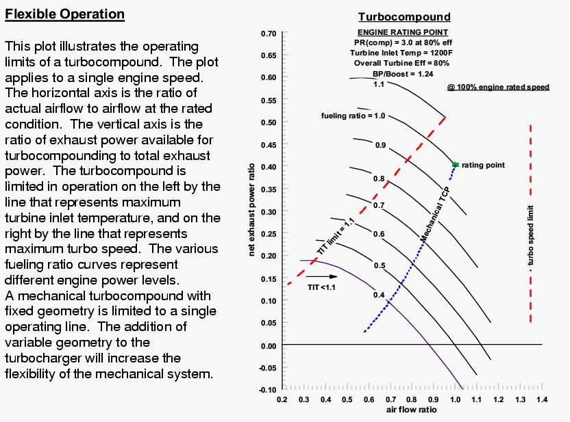
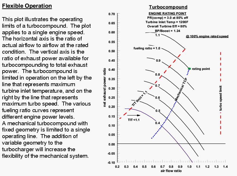
It takes two to tango. It take heat and RPM to fail. It matters
not which one you limit. Here is a chart from Caterpillar that illustrates
that point. On the right is the RPM limit. On the left is the heat
limit. Somewhere in between the turbine will fail from a COMBINATION of heat
and RPM. The high energy pulse from the rotary exhaust does not help
the matter. It may be shocking the blades into resonance. Chart 1
Point 2)
Most turbo charger set ups are for cars
or trucks. A turbine is chosen such that it generates way more max HP
than the compressor needs for a given amount of boost. This is
done to allow the turbo charger to rapidly accelerate when the driver
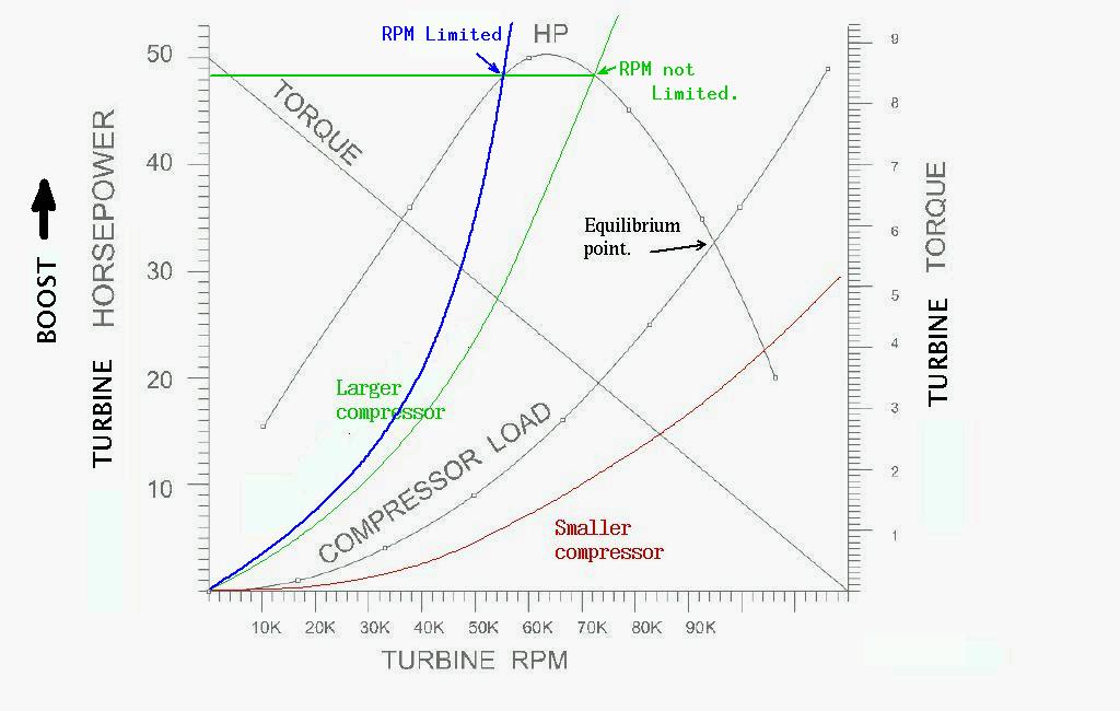
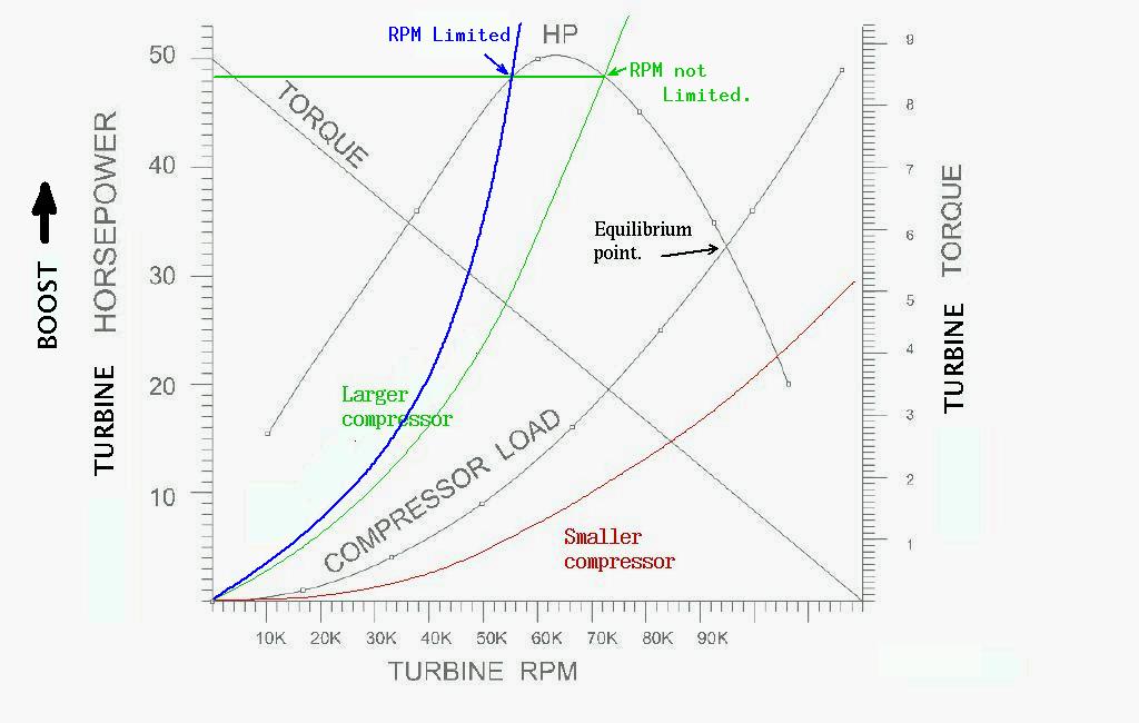
floors the go pedal. The trick is chose a compressor load
that matches the peak HP of the turbine which happens at
about half of max RPM.
IMHO so far we have not got there yet. IMHO so far our turbines have had way
too much power. IMHO they have gone way past the power peak RPM and have driven
compressors that are too small. Dave had a company put a larger compressor
on his turbine. Unfortunately they modified the turbine at the same time to
increase its power. Not what he needed. Never the less the combination was
good enough to slow the turbo charger and get the life up from about two hours
to 120 hours. There was no change in the EGT's. I still say he needs a larger
compressor yet. IMHO he will get more boost and slow the turbo charger RPM in the
bargain. It is easy to over speed a turbine if the load is not there.
The stress on the blades is the mass of the blades times the circular
velocity of the blades SQUARED divided by the radius.
Note that if we were on the exact other side of the HP curve the
the HP and compressor load could be exactly the same while the RPM would be
drastically slower. The boost would be the same. The RPM would be limited
just like a prop limits the RPM of an aircraft engine. We need a turbo
tach to figure all this out. We need a turbo tach to find out what side
of the curve we are on. Chart 2.
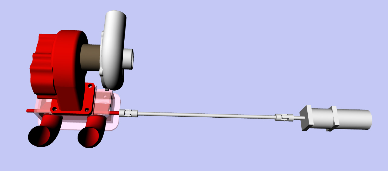
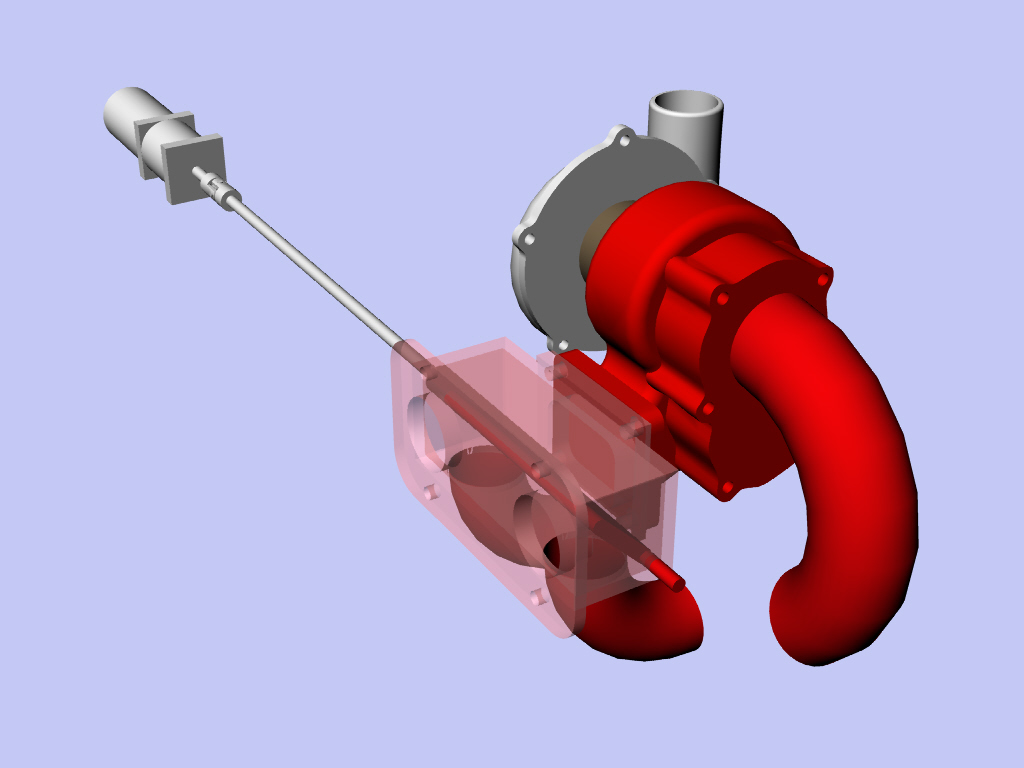
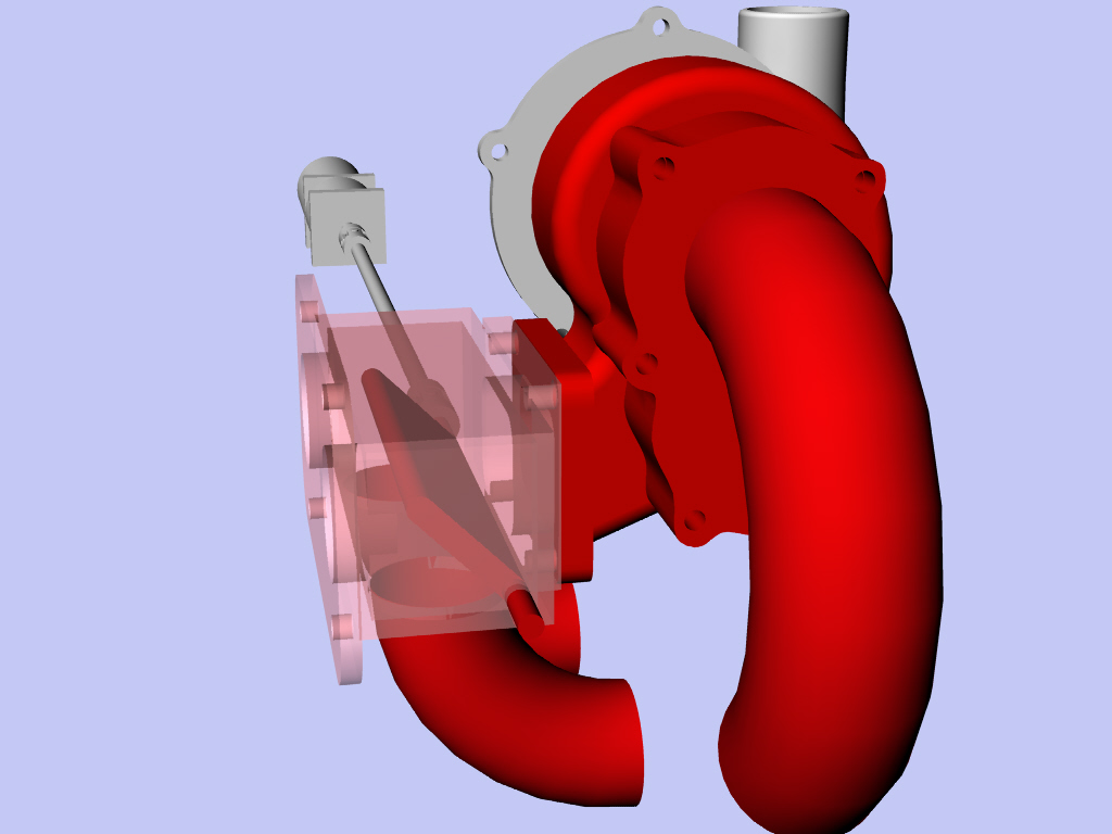
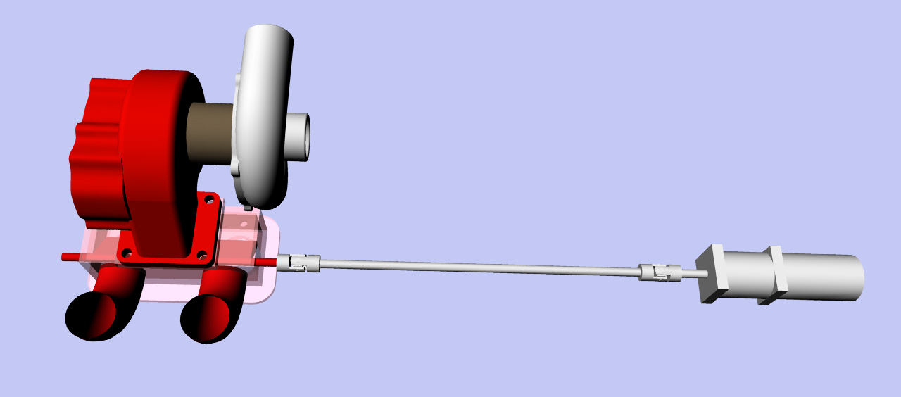
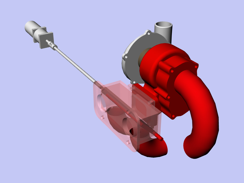
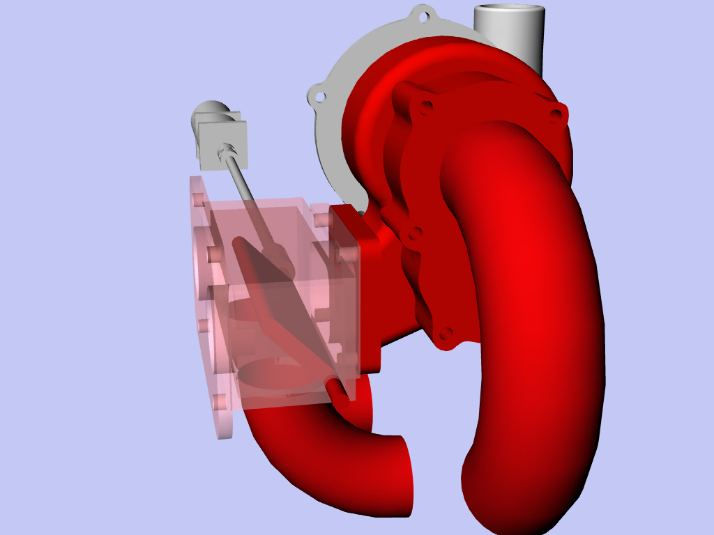
In the mean time this is my latest diverter valve/manifold design. It is better than
a waste gate as it has the option of turning the turbo charger completely off.
When it does it diverts the gas to a straight exhaust pipe. Handy if the turbine
fails again if we don't get it right. Actually it can divert a portion to
the exhaust pipe and a portion to the turbo or all to the turbo. The turbo is
off set from the rotors so supersonic pulses are discouraged from getting
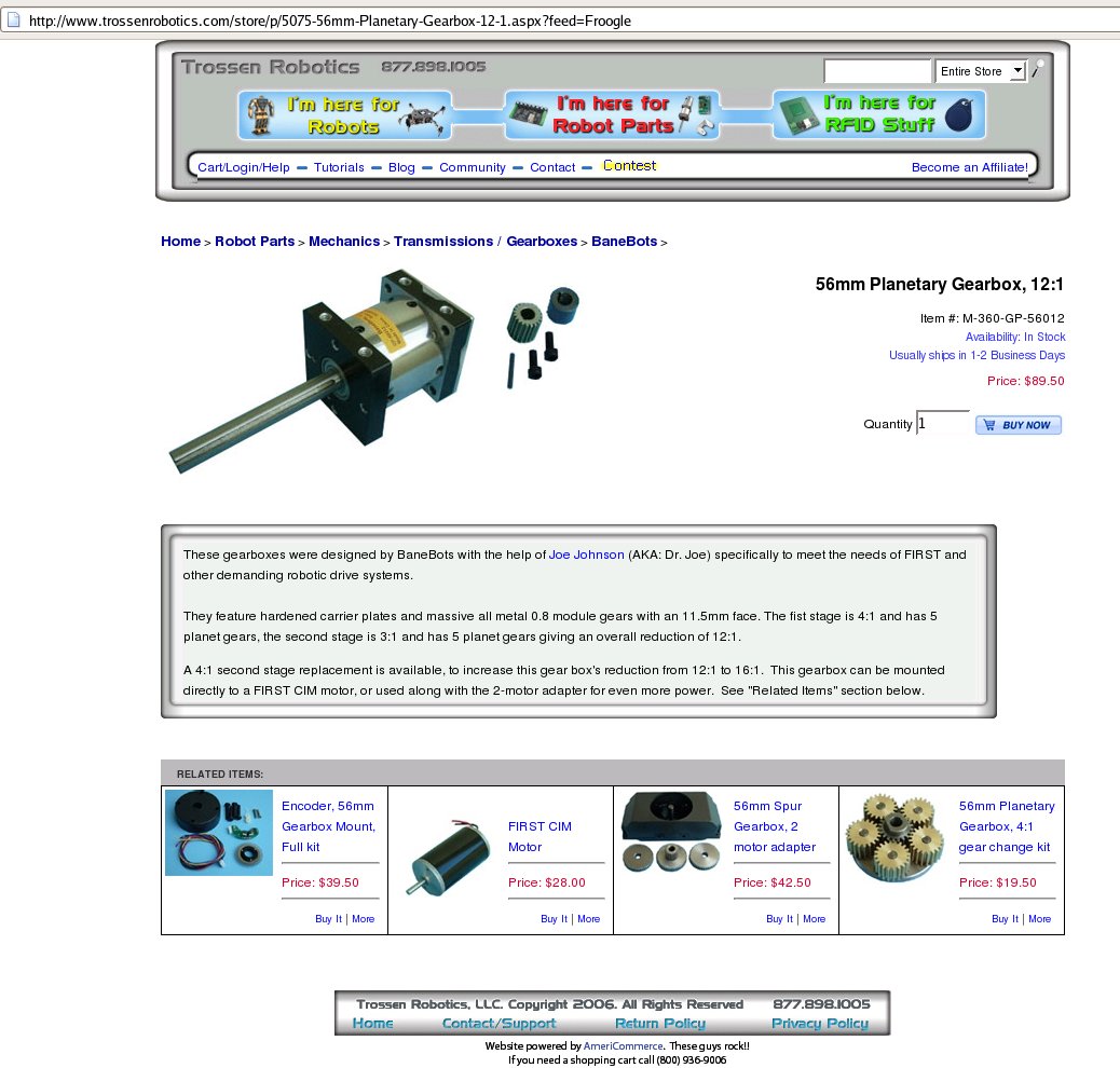
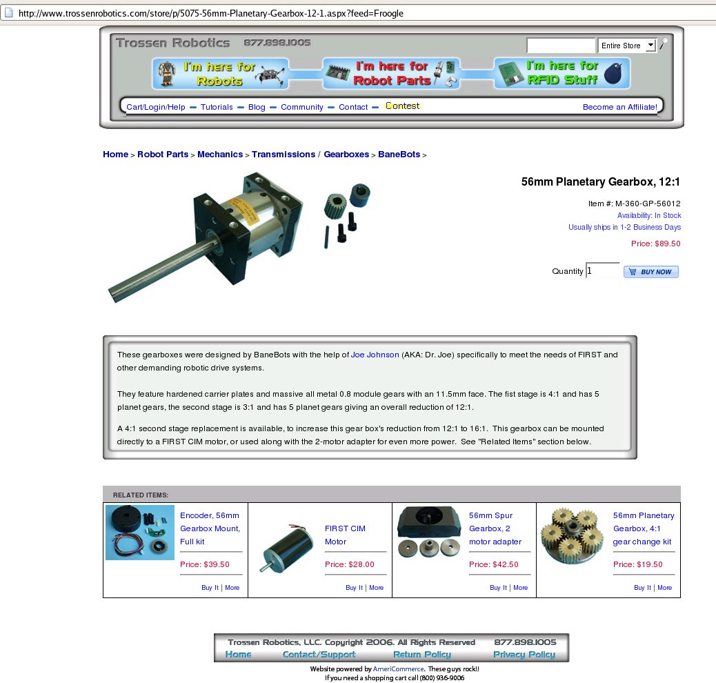
to the blades. It is controlled by an electric motor and a 16:1 gear box.
Something like 500 foot pounds is available in theory to control the
diverter valve. Way over kill. It will never need that much torque and
the motor will never draw max current. It will stay where you set it
due to the high gear ratio reduction.
Paul Lamar ...No rotor no motor.
The Rotary Engine NewsLetter. Powered by Linux.
ACRE NL web site.
http://www.rotaryeng.net
Youtube key word UTUBPLEASE
Copyright 1998-2008 All world wide rights reserved.