YES Steve,
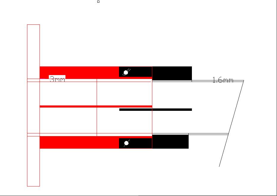
The short header tube has the collar (with dog leg or L shape)
welded to it.
The exhaust pipe has a collar and small extension welded to it.
The exhaust pipe is also flared to accommodate the short header tube.
The L shaped ( dog leg) holds the two together. There would be
movement
between the two pipes which would allow for differential expansion and
contraction, which I believe is your primary concern.
This could design could have many variations, like more than one dog
leg and
springs, but I've never liked springs around that sort of heat.
I believe it's a simple yet quite effective design that can be
handled by
the novice.
Here is another by Bill Jepson, if you were concerned about gas
leakage.
Could be considered simpler.
George (down under)
What a great drawing........
The springs hold up just fine actually, however, if there is a lack of
comfort in that area, flat straps can be used with deformed nuts on
bolts like "Jet nuts" tightened to just touch and no more. So movement
is possible but he joint cannot be pulled open. If very stiff coiled
springs are used, a second hole in each tab is used for a doubled strand
of safety wire run through the spring but left just slack, to retain the
joint in the event the spring would go soft, or fail outright, and then
the spring pieces would be retained on the wire.
Also a more compact joint can have the tabs pass tight against each
other overlapping, and a common hole can share a loose nut and bolt as
above. Have the tabs pass on alternate sides of each other, so you can
still twist the tubing when disassembling it.
The Dutch clamp should be used where disassembly is not a common
occurrence, but still required. Once over tightened, the clamp is
powerful enough to reduce the tubing diameter, and make removal difficult.
Lynn E. Hanover
Lynn,
Here's my quick and dirty drawing of my latest idea, although not at good as
Bill's I do my best.
I have taken Bill's idea and combined it with my own by having my small
support corner flanges extend out to overlap flanges on the exhaust tube -
now referred to as a FIN.
This does a number of things:
1. It provides additional welded area support (on the exhaust flange)for
the thicker stub tube - at the base of the FIN.
2. The weld continues over the stub and stregthens the stub ( length wise)
as well .
3. There could 3 to 6 fins if so desired.
4. The fins could be considered heat sinks as well.
5. The fins could be double drilled to accommodate the bolts and safety
wire.
To make it easier, the slip over section of the exhaust could be welded on
rather than having the SS expanded - but either would do.
I think this incorporates everyone's ideas. The dutch clamp and double
sleeve could also be used if considered necessary.
Personally I will try the simple method first.
George ( down under)
The Rotary Engine NewsLetter. Powered by Linux.
ACRE NL web site.
http://www.rotaryeng.net
Youtube key word UTUBPLEASE
Copyright 1998-2008 All world wide rights reserved.