Paul, the following statement was posted on the
Tailwind discussion
group. Do you think it is true and how would you
explain such
performance? Jerry
Just found this: lsecorp.com, then click on news on
left side. Klaus
Savier flew the Vari-eze nonstop from Santa Paula,
CA to Panama City,
FL, 1985 statute miles in 8 hrs 58 min on 25.8
gallons. Slightly under
80 miles per gallon.
Its true. Klaus had a strong tail wind. As I recall
he also had oxygen :)
He leans his engine severely and advances the
ignition. He also uses
a high energy multi-spark capacitor discharge
ignition system to
fire the lean mixture. Another factor is the
aircraft is highly
refined aerodynamically. Yet another factor is he
uses solid state fuel
injection but it is not computer controlled. Cheap
analog circuits (cost $1 each)
called 555's or something similar are used to change
the pulse width
on the electric injectors. Each cylinder gets the
same amount of fuel. He may be
able to adjust the fuel on each cylinder
individually according to the EGT. You have
plenty of time up there to diddle around.
Paul Lamar ...No rotor no motor.
Paul,
How do the chips know how much fuel to deliver does
it work on RPM or throttle position or something
like that?
George ( down under)
I am not exactly sure about all the details but with
a fixed pitch prop you could probably
get away with RPM alone. You only really have two
RPM points where you need precise
mixtures, climb and cruise. You could manually
adjust for those two conditions.
Paul Lipps probably designed the system. The
attached schematic diagram for a rotary
uses a throttle pot. I have attached another 3D
showing a way to make a throttle pot device.
Freescale manifold pressure sensors could also be
used.
Paul Lamar ...No rotor no motor.
Paul,
You did it again! (I am referring to a correction
sent about 6 months
ago.)
Check your 555 graphic in above email.
Don't put TWO tabs on your "timing wheel" - use just
ONE. The ONE tab
needs to rotate around (at e-shaft speed) to trigger
the two separate
injector circuits 180* apart.
As shown in your graphic, you will fire both
injector sets
simultaneously (for rotor 1 and rotor 2) twice per
revolution.
Normally I would just lurk, but the Wankel confuses
enough people
already. (It shouldn't - it's simpler than a piston
engine.)
FWIW.
-Vince Orton
True. Sorry. Is that your diagram or mine Vince?
Well I had it lying around so I used it. The subject
only comes up once a
year or so. I probably never bothered to redraw the
diagram.
How's this?
There is another mistake in that two injectors are
fired for each rotor
while only one power transistor is used. I would use
one power transistor for
each of four injectors instead.
----------------------------------------------------------------------
Here is some more info on the little jewels.
--
Paul Lamar ...No rotor no motor.
And for a negative opinion:
------------------------------------------------
Subject: Super simple 555 based fuel injection
system
From: Rotary Engine <rotaryeng@earthlink.net>
Date: Tue, 02 May 2006 16:14:19
I have actually built an electronic fuel
injection system. It is a lot
more complicated than this.
You have to change the duty cycle with manifold
pressure. The engine
won't run unless you do this, at least in a
simple fashion.
You have to change the duty cycle with RPM.
Again, the engine won't run
unless you do this at least in a simple
fashion.
The throttle position alone isn't enough to set
the duty cycle. The
engine won't run.
In theory, you could sense the intake air mass
flow and set the duty
cycle based on that alone. (Manifold pressure
and RPM together allow you
to estimate mass flow.)
I think you would be better off with a
hand-controlled needle valve than
you would be with a 555 based EFI.
Bill Dube'
---------------------------------------------------
Bill overlooked the fact that the pulse rate is
directional proportional
to RPM as there is a shaft sensor that triggers the
555.
He may have a point about throttle position. Perhaps
it is easier
and cheaper to use manifold pressure to change the
pulse width.
I'll look into to it and see if I can come up with a
circuit that works.
I don't want to use mass air flow alone as that
implies mass airflow sensors
that restrict the intake flow.
--
Paul Lamar ...No rotor no motor.
paul,
i'm no fuel injection expert, but a reference i have
calls your system an "alpha-n" system.
gary in midland
--------------------------------------------------
page 9, fuel injection basics, petersen publishing
"alpha-n
"there is one other efi control system that is
generally used only in racing called an alpha-n
system. this control system's major inputs are
throttle position and rpm. this system was developed
because race engines often operate at idle and part
throttle with very little manifold vacuum. this makes
using a map sensor difficult. this system is less
precise than a speed density or maf and is therefore
generally only found in racing or heavily modified
street engines with big camshafts. a map sensor can
still be used with alpha-n, but it is generally
employed as a barometric pressure sensor to detect
altitude changes."
The mass airflow sensor is probably the easiest way to control
a 555 system. You do need the e-shaft trigger but the mass air flow
sensor can control the pulse width. It is possible to have high
RPM with low fuel flow if there is no load on the engine however you
don't see that in aircraft engines with fixed pitch props.
Load is probably proportional to RPM squared.
Just about everybody has one of these Mazda mass airflow sensors
lying around.
--
Paul Lamar ...No rotor no motor.
Paul,
A better mass air sensor to use is the unit found in ford V8 trucks from 97
and up. Many of them in salvage yards. They were for engines of 220 to 260
hp putting them in the flow range we need. Also very light and reliable.
Just don't get one from the supercharged trucks, as they are 90mm diam.
Larry
Thanks for the tip Larry. Are they mechanical like the Mazda or electronic?
The electronic are harder to use as they are tougher to interface with
the 555. The Mazda unit is just a trap door connected to a pot.
--
Paul Lamar ...No rotor no motor.
Paul,
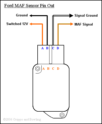
Pin out attached.
Larry
The problem is 5 volts is high airflow and the 555 fed 5 volts would be narrow
pulse. Zero volts would be a wide pulse out of the 555. What you one must do
is come up with a circuit that reverses that and probably increases it to 12 volts.
Using the Mazda simple device you just wire the pot backwards.
I am not saying it can't be done. Just more trouble.
--
Paul Lamar ...No rotor no motor.
The Rotary Engine NewsLetter. Powered by Linux.
ACRE NL web site.
http://www.rotaryeng.net
Youtube key word UTUBPLEASE
Copyright 1998-2008 All world wide rights reserved.