Paul,
A better mass air sensor to use is the unit found in ford V8
trucks from 97 and up. Many of them in salvage yards. They were for
engines of
220 to 260 hp putting them in the flow range we need. Also very
light and reliable. Just don't get one from the supercharged trucks, as
they
are 90mm diam. Larry
Thanks for the tip Larry. Are they mechanical like the Mazda or
electronic? The electronic are harder to use as they are
tougher to interface with the 555. The Mazda unit is just a trap door
connected to
a pot.
--
Paul Lamar ...No rotor no motor.
Paul,
Pin out attached.
Larry
The problem is 5 volts is high airflow and the 555 fed 5 volts
would be
narrow pulse. Zero volts would be a wide pulse out of the 555.
What you
one must do is come up with a circuit that reverses that and
probably increases it to 12 volts. Using the Mazda simple device you
just wire the pot backwards.
I am not saying it can't be done. Just more trouble.
--
Paul Lamar ...No rotor no motor.
I would call such a circuit an op-amp. Inversion and scaling
in one step.
Bob W.
--
N93BD - Rotary Powered BD-4 -
http://www.bob-white.com
3.8 Hours Total Time and holding
Cables for your rotary installation -
http://roblinstores.com/cables/
Sounds like you are the man for the job Bob. Care to do a
schematic and
make a prototype on a plug board?
Here is what the Mazda unit would look like along with the
original Chaparral 2D ram air box from 1965.
--
Paul Lamar ...No rotor no motor.
OK, I'll draw up something 0-5V in, 12-0V out and build a
breadboard circuit. It may be a few days as I'm trying to finish up a
couple of other projects.
Bob W.
--
N93BD - Rotary Powered BD-4 -
http://www.bob-white.com
3.8 Hours Total Time and holding
Cables for your rotary installation -
http://roblinstores.com/cables/
Great Bob.
Thanks.
------------------------------------------------------------------------
Here are the pin outs and resistance data on the Mazda
mechanical air flow sensor if you want to keep it as simple as possible.
The sensor air flow area is about 5 square inches so it is a
bit of a restriction
on a P-port engine with two... 1 7/8 ID runners have 5.52 square
inches
total area. How much that is going to affect the power is hard
to say.
I intend to get the prop dyno working with the P-port RX8
engines so perhaps I will find out.
The resistance varies between 50 and 500 ohms so the 555 pulse
width with a 100 uF cap should be in the right range (1 ms to 50 ms) I
am not sure this
is going to work. It would be better if the pot was higher
resistance.
I'll have to mock it up on the bench.
----------------------------------------------------------------------------
I am coming around to the hot wire and op amp approach.
I suspect that a 100uF cap may not be practical for drift
reasons and temperature
change reasons.
Here is a great little opamp calculator.
http://www.bcae1.com/
Scroll down to about the middle of the page.
It will also work with a FreeScale MAP sensor if you don't want
to use
a mass airflow sensor.
Here are hot wire sensor pictures from a Ford Escort.
--------------------------------------------------------
Bob, what do you think of this idea? Small daughter PC boards
50 mm (2") by 26 mm (1") with
the op-amp, the 555 and the FET on them for each injectors.
Modular. If one fails
you carry a spare and plug it in. Makes things easier to
trouble shoot as well.
The 50 by 170 mm (7") 3 rotor motherboard can have the pilot
controls on it such as the start
enrichment switch and the leaning pot. The whole works can be
mounted behind the instrument
panel. This should drastically reduced the wiring the installer
must do.
Also I am thinking that coax cable could be used for all other
wiring. Coax is shielded
and if it is Teflon it is hard to burn through in a fire.
Nothing says you cannot
use coax for DC. Also BNC connectors are cheap and they are
shielded.
It is about a buck a foot but cheap insurance against RF
interference.
Lots of people have had problems with that lately.
Paul Lamar ...No rotor no motor.
I don't think coax is necessary as I don't think any other part of
the circuit is going to be a controlled impedance environment. Coax is
useful (required) where power transfer is critical from one device
to another (antenna systems and other high frequency systems (MHz+).
Tefzel (standard Aircraft Spruce) shielded wire should be perfectly
suitable for the signaling in this kind of system. The power and
ground don't need shielding - but the wire needs to be plenty big, and
there should be some filtering on these leads. It might be a good idea
to shield the signal (sensor) and injector wires. Ground the shield
only at the control box.
Regards,
Matt-
All true Matt but I like the sledge hammer approach to RF
interference. Do IT all in coax :) Using BNC connectors it is easy to
disconnect things
for trouble shooting and the grounding is built in. Cost is the
only drawback but this is an airplane for heavens sake :)
With the simple 555 system you have two wires coming from
the two mag pick ups and four wires going to the injectors. Of
course the top
of the injectors are connected to 12 volts. The FET's merely ground
the bottom
side of the injector coils.
BTW it is very very simple to mechanically change the injector
timing by rotating the
mag pick up steel plate relative to TDC.
--
Paul Lamar ...No rotor no motor.
I don't like fat coax because it's heavy and bulky... I have seen
plenty of improperly installed BNC connectors. DB (15,25) connectors
are easy to install and remove as well. But, it's your airplane.. :)
Matt-
RG59/RG58 coax is only about .2 inch in diameter.
Probably a dozen people have had trouble trying to solder a zillion
wires to DB connectors. Yes I know you can get crimp on style but the
wires are two small for the current levels we are running. The shock
and hold injectors require about six amps. People building airplane are
not necessarily electronic technicians. We must keep it very robust and
very very simple. You want DB buy Tracy.
--
Paul Lamar ...No rotor no motor.
Hi Paul,
The daughter boards look good, and having the modular unit with FET
co-located with the injector sounds good. I agree with Matt though
that the coax won't buy you anything. A twisted pair of 20 AWG Tefzel
should be more than adequate. Keeping the circuit low impedance also
reduces problems with RF interference. I do agree that the D
connectors are not the most robust choice and shouldn't be used in the
engine compartment in any case. If you really want to keep it simple,
just put two holes in the PC board and solder in the signal wires from
the controller. If you want a connector for ease of replacement or
maintenance, the Delphi Metri-Pack connectors are a good choice. The
are available in any number of pins needed, lock together, are sealed,
and have been used in millions of GM cars for the coils and other
sensors. The pins are crimped on and the wires are well supported.
Molex also has a new line of sealed connectors, but I haven't looked at
them yet.
For the first step, I'll build the op-amp on perf board. I think I
have some 555's around also. If not, I can pick them up. I suspect
the output will have to be tailored somewhat through experimentation.
Packaging details can come later.
Will you need four of these units to do your testing?
Bob W.
The point with the BNC is sooner or later you will need to check injectors.
The easy and fast way is disconnect the BNC and ground the center connector.
The injector should click. Doing that for six injectors takes time
if they are hard wired. It is also a pain to ground the shield on a
bunch of wires. The BNC connector does that automatically.
Not everybody is going to appreciate this but once you try to
wire up one of these conventional EFI systems (and I have) it becomes
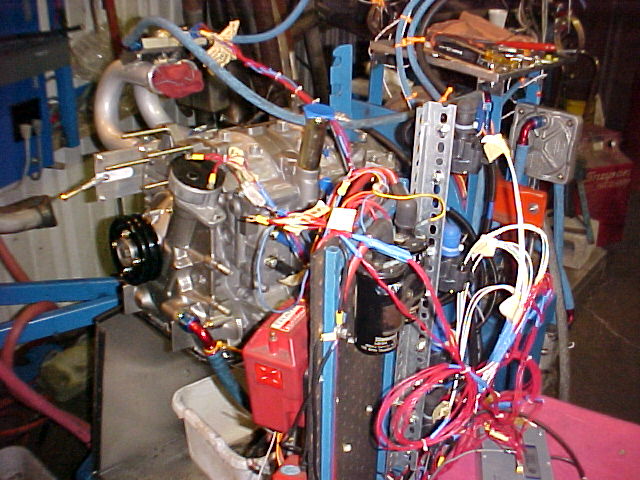
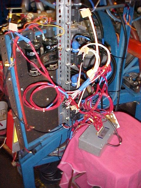
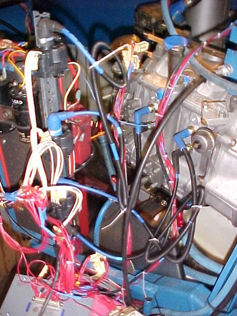
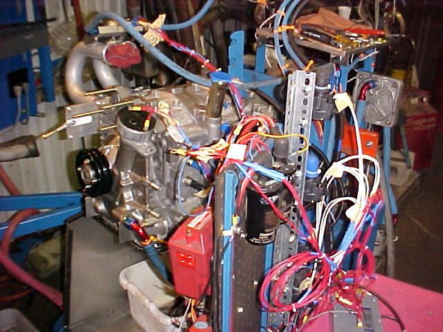
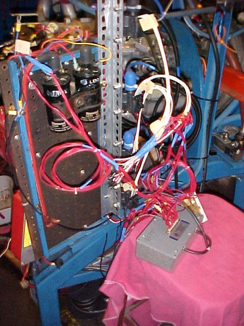
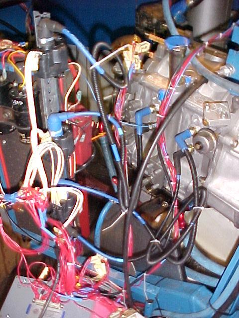
apparent there needs to be a better way. Here are some shots of Tracy system
on the dyno with Mark's p-port. Mark did the first go around on the
wiring harness and I redid it.
The rapid disconnect of one wire at a time will do wonders for trouble shooting.
Yes I will need four Bob. Thanks. I'll do a lot on the bench as far as flow
assessment is concerned so I'll be in the ball park when I install it
on the RX8 p-port engine. I have about given up on conventional
dyno's so I will be using my prop dyno. Closer to the aircraft real world.
--
Paul Lamar ...No rotor no motor.
The Rotary Engine NewsLetter. Powered by Linux.
ACRE NL web site.
http://www.rotaryeng.net
Youtube key word UTUBPLEASE
Copyright 1998-2008 All world wide rights reserved.