-------- Original Message --------
Subject: Building a 555 EFI system. Step 2
Date: Sun, 13 Jul 2008 19:54:19 -0700
From: Rotary Engine
<rotaryeng@earthlink.net>
To: AAA Put this in the To box
<rotaryeng@earthlink.net>
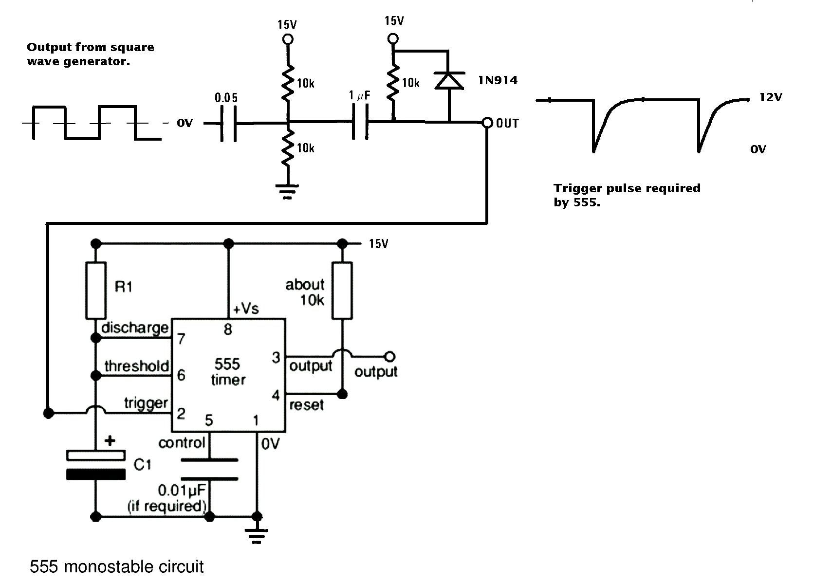
One of the first things to do is simulate the signal from a
crank angle sensor. The 555 requires a negative narrow
pulse to trigger it. Most low cost signal generators put out
square waves or sine waves. One needs to convert the square wave
to a negative going narrow 12 Volt pulse. This simple circuit will do
the trick. It works from 1000 RPM to 11,000 RPM.
---------------------------------------------------
Here is step 2.
R1 will be replaced by Bob's op-amp circuit with control from
a mass airflow sensor.
C1 is about .1 uf at the moment.
The scope is set to 10 msec per division so the positive output
pulse is about 9 msec long. Goes high. The bottom of the
screen is 0 volts. Lower trace.
Upper trace shows the negative going trigger pulse.
The trigger is coming in every 40 msec or about 25 times
per second or 1500 RPM.
So far this is an extraordinarily cheap and simple EFI system.
In fact this beats the cost of an Ellison aircraft carb or a
$1000 Weber for that matter by a factor of half the cost.
That includes $200 or so for the four injectors.
Step 3 will be adding the FET and the injector.
--
Paul Lamar ...No rotor no motor.
Hi Paul,
I've bread boarded a circuit that looks like it will do the job. I
don't have the right resistors, so the correct values were obtained by
series/parallel conglomerations. I can pick up some stuff tomorrow and
send you a prototype Wednesday. I'm just building the op-amp
interface as you seem to have everything else in good shape.
Do you need one prototype for your bench test setup or four prototypes
for the bench test setup? I need to order more op-amps to build 4
circuits. Mouser should have them to me by Wednesday or so.
Are you planning on getting PC boards made for the engine tests?
ExpressPCB will make 3 board 3.8" by 2.5" for $51.00. Two or more
circuits should fit on each board. It makes for a more reliable test
setup for nominal cost.
Bob W.
Just one Bob.
I have been fooling around with another power supply
feeding voltage into pins 6 & 7. I can vary the pulse width by changing
the voltage but it is very sensitive and only works over a very narrow range
from about 9.5 volts to 10.5 volts. What we need to replace R1 is a voltage
variable resistor. Have you had any luck in this regard? Will an FET work?
Can you send me your schematic?
BTW the Mazda pot type mass airflow sensor works fine.
---------------------------------------------------------
Kill that. I am not supposed to be feeding voltage to pins 6 & 7.
I am supposed to use pin 5 Duh! :)
--
Paul Lamar ...No rotor no motor.
The Rotary Engine NewsLetter. Powered by Linux.
ACRE NL web site.
http://www.rotaryeng.net
Youtube key word UTUBPLEASE
Copyright 1998-2008 All world wide rights reserved.