Here is the Ford hot wire version of the mass
airflow sensor.
About $10 bucks in a pick your own part junkyard.
You will need a special anti tamper screw drive to
get it
out of the aluminum housings. If you buy the
aluminum housings
it could cost you $80 as the junk yard recycles
those.
Thank to Larry Childs for the pin out.
These are very sensitive to dust in the intake
system.
In fact my Mercury Cougar would foul every year or
so even with an air filter. Had to take it out
and clean it with a tooth brush and acetone.
Took about five minutes. I suspect the filter was
shedding
fiber particles. You could not see the particles
with the naked
eye. I had to use a jeweler's loop to see the
offending particles.
The OBD II check engine light would come on and the
dealer
wanted $90 just to hook up his computer. Then he
wanted
$300 for a new mass air flow sensor not counting
labor.
I don't think that included the aluminum housing :)
Just about any hot wire sensor can be used as Bob is
designing
an op-amp so the gain can be changed to tailor the
unit to your
needs.
Testing this is going to be tough. Best thing is
hold
it out the window of your car while doing 120 MPH :)
--
Paul Lamar ...No rotor no motor.
paul,
i had a ford fuel injection book and looked in and
found these pages about the ford maf
gary in midland
Paul ,
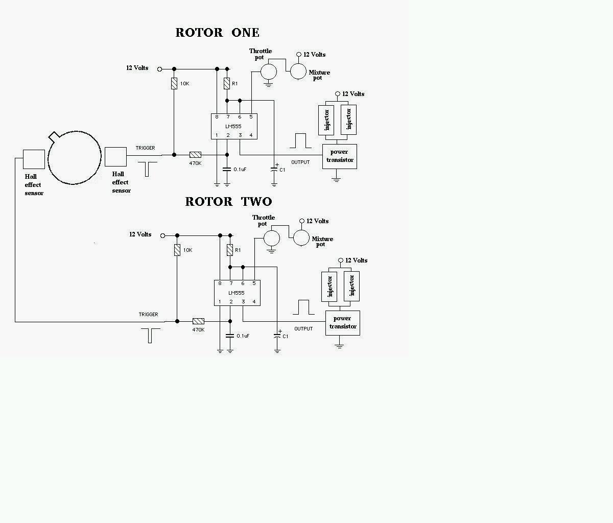
I understand the how the 555 injection controls works with MAF and that
is the good point.
Partial throttle will change flow so the MAF will reflect this.
Different levels of boosts will change the mass of the charge.
Temperature also affects mass.
RPMs effect the best moment and duration to inject however. As I
understand it the 555 system you are advocating is simply a PWM chip
driving a FET switch. That is fine but where is the logic that
increases the fuel quanity in comparison to the engine demand? You
still have to create a curve of PWM verses RPM right. Any op amp sending
a signal from the timing wheel to the 555 is going to be linear right?
Ie as rpm increases the signal voltage increases.
So how does the MAF sensor interface? It modulates the signal from the op
amp?
Doug in Japan.
The pulse rate of the 555 is directly proportional to RPM.
The pulse after all is triggered by the crank angle sensor.
The pulse width is constant so the fuel supplied will also
be a linear function of RPM. The air required with no load
is also a linear function of RPM in this case.
You can verify this in your car. With the TX in neutral
it does not take much throttle opening for the engine RPM to hit redline.
That would be fine and dandy if the load on the engine was also
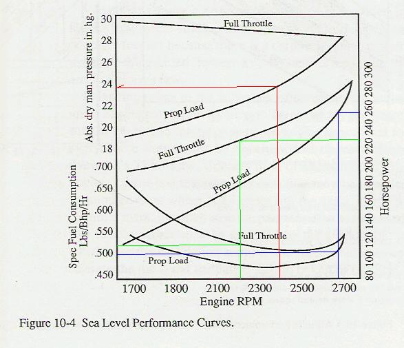
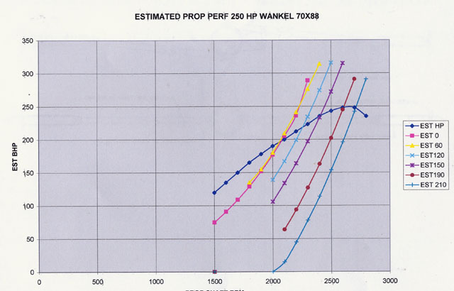
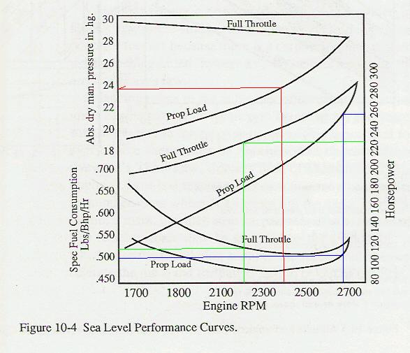
a linear function of RPM. That is not the case with a fixed pitch prop.
The air required and fuel required must be matched to the load.
The mass air flow sensor measures the air flow regardless of the RPM.
Fixed pitch prop load is proportional to the square of RPM
up to the point where the tips go supersonic so we must also
increase the pulse width to match the load increase.
This is what makes an aircraft EFI system so much easier to
design than that for a car with widely varying loads at different RPMs.
IMHO the computer controlled EFI for an aircraft engine is way over kill.
BTW the sound an engine makes on the dyno changes drastically as
the load increases at a constant RPM. The technical term is called "full chat" :)
It is rather impressive to be around an engine on the dyno at full chat.
For the above reasons it makes more sense to do aircraft engine EFI development
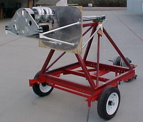
on a prop dyno rather than a car dyno. I am picking up my p-port RX8 engine at Mazdatrix
and will test the 555 system on my prop dyno.
Paul Lamar ...No rotor no motor.
The Rotary Engine NewsLetter. Powered by Linux.
ACRE NL web site.
http://www.rotaryeng.net
Youtube key word UTUBPLEASE
Copyright 1998-2008 All world wide rights reserved.