>>>>Paul,
>>>>
>>>>Check these out. I have purchased four of them. Fast, small, large
flow
>>>>and, are OK for flex fuel. Simens DEKA IV. Four little holes with
good
>>>>performance even at low flow rates.
>>>>
>>>>Specs here.
http://www.bmotorsports.com/shop/product_info.php/cPath/144_146/products
_id/448
>>>>
>>>>Calculation. Given max. injection duration (intake cycle) equals <120
>>>>degrees. Actually about 105 degrees to avoid port overlap. At 6,000
>>>>rpm, it requires 1/100 of a second or 0.01 second. to complete 120
>>>>degrees of arc. Think of this as the intake event.
>>>>
>>>>These injectors turn on in 1.14 ms and off in .85 ms. Total is 2.99
ms
>>>>or call it 3 milli secs.
>>>>
>>>>or 0.003 of a second. Even at 8000 rpm and 100 degrees of injection
>>>>duration (delay start of injection until exhaust port closes), there
is
>>>>still gobs of time to inject the require amount of fuel needed while
>>>>keeping the duty cycle low. If one injector craps out the remaining
>>>>injector duty cycle can be doubled without a sweat.
>>>>
>>>>Doug in Japan
>>>>Wow!!! you got that right Doug. 60 pounds an hour is 10 gallons an
hour
>>>>per injector.
>>>>40 gallons an hour for four. At a BSFC of .6 that is 400 HP!!!
>>>>
>>>>Great injector. Small too. Ideal for P-ports.
>>>>
>>>>I am sold. I am buying four. No use messing around with marginal RX8
>>>>injectors.
>>>>
>>>>--
>>>>Paul Lamar ...No rotor no motor.
>>>Paul,
>>>
>>>Great choice. You will enjoy them. Some people I know run them at
>>>higher PSIs and claim as much as 90 lbs/hour per injector which is way
>>>over our needs.
>>>
>>>For direct placement in the housing this is what I plan to try:
>>>
>>>Bore two angled holes in the rotor housing on each side and parallel
to,
>>>the oil injector boss. Next lightly press and ring weld two alumunum
>>>25mm dia. 15mm long plugs in the holes with the low melt point new
alloy
>>>brazing. After that, end mill bore a 19mm dia hole through the center
>>>of the plugs and bottom it out against the back side of the metal
rotor
>>>housing line. Next take a 19mm OD dia/ 15mm ID pipe and ream the
>>>inside out a hair as well as turn the outside down for clearance. An
>>>upper and lower (inside- outside) O-ring groove needs to be cut on the
>>>pipe. The injection hole will be about 5mm dia and slightly tapered
from
>>>the inside. This will put the injector close to the inner housing to
>>>take advantage of the wide spray cone, but far enough back not to
>>>contact the Apex seal. The 19mm pipe complete with O-rings is hand
>>>pressed into place. Properly done it can`t leak water either into or
>>>out of the housing. If desired, a set screw can be installed in the
>>>outer boss perpendicular to the injector mount pipe to assure it does
>>>not move. Finished with the injector installed into this pipe,
bring
>>>the wire and fuel rail connector real close to the housing so I believe
>>>the manifolds can wrap over head. Wires and well and fuel lines can
>>>come from the cool side.
>>>
>>>The challenge is adjusting the best moment to begin the injection
event,
>>>but the advantage is that we put the small slide throttles ( yes thats
>>>plural) right smack up against the housings.
>>>
>>>I having a big steel jig being made now by the local shop so I can can
>>>rotate the rotor housings to one of five fixed positions within it
>>>accurately and repeatly. I need various holes on each side and top of
>>>the test engine. I`ll send pictures when the jig is done
>>>
>>>
>>>Doug
>>>IMHO I think you will be disappointed in relatively low pressure (50
psi)
>>>direct injection
>>>Doug. The fuel does not have enough time to evaporate. The new direct
>>>injection
>>>diesel systems are using upward of 20,000 psi. First picture. There is
a
>>>measurable decrease
>>>in BSFC by injecting at the start of the runner. Second picture. Racing
>>>Beat reported
>>>this during dyno runs. Also the fuel cools the air in the runner
>>>increasing power.
>>>
>>>No harm in trying again however. One can always go back.
>>>--
>>>Paul Lamar ...No rotor no motor.
>> Paul,
>>
>> We have been down this road before I think. It seems over the years I
>> have heard a lot of conflicting opinions on the subject. Case in point
>> Mistral got their best BSFC injecting near the housing in the inside
>> ports, after the tried out near the ends as you suggest. Steve Beckham
>> and Everetts had good results (with other side effects of course) by
>> injecting against the hot rotor directly thus vaporizing it the spray
>> but perhaps losing some fuel to the exhaust., Lastly, the Lemans
engine
>> had the injection right after the slide throttle and perhaps three
>> inches from the inside port. None these situations had injectors that
>> could deliver fuel so rapidly as the Deka 1V so one half of the time
the
>> Mazda injectors are spraying into a closed chamber before the port
>> opening causing the fuel to hit the walls and condense.
>>
>> Their are advantages and disadvantages of course for, Correct me if I
am
>> wrong but the gases in the chamber rotating from the intake port to
>> about 120 degrees after that is not experiencing positive pressure yet.
>> In fact when the injection event starts, and there is an hot rotor a
few
>> inches, away, the intake chamber is a minus pressure.
>>
>> Yep injecting out near the bell mouths would definitely cool the
charge,
>> and may even cause condensation which is of course counter productive.
>> Works in racing car environments obviously because they have a
>> tremendous amount of heat contained in a fairly tight cowling. I won't
>> have that problem with only a few inches of boost, Teflon manifold,
>> ethanol based fuel E-85, and having an intercooler in between. Sorry I
>> don't particularly like the idea of creating an explosive mixture in a
>> thin walled container, that is open to the atmosphere all of the time.
>> One backfire and the manifold and possibly a lot of cowling is toast.
>>
>> As I understand it, for direct injection engines, the pressures have to
>> be enormously high because the injection occurs when and where the
>> compression is at it's highest.
>>
>> But in any case you are correct, direct low pressure injection is worth
a
>> try and I can always mount them outside on the manifold if I'm not
>> satisfied with results. The name of the game is striving for complete
>> fuel burn whether that comes from speeding up the flame front by adding
>> a smiggen of H202 gas on the end of the intake stroke or increasing the
>> vaporization of the fuel.
>>
>> Doug.
>> The short pulse idea is interesting. I think the Lemans engine
mentioned
>> injecting the fuel at the start of the runner but they chose
>> the closer position for throttle response reasons. In a road racing
>> situation
>> good throttle response is critical. Also it was more difficult to
>> fabricate because
>> of the changeable runner length. In Formula 1 the runners are only
inches
>> long
>> as the RPM is 19,000. In any event the BSFC differences are minor.
>>
>> I am not advocating injecting the fuel before the intercooler.
>>
>> Early diesel engines worked on moderate pressure. Nowhere near 20,000
psi.
>> 20,000 psi is a relatively recently development where engine oil
pressure
>> is
>> used to enhance fuel pressure in special 2 stage fuel injectors.
>>
>> Lets run through some numbers to put things into perspective.
>>
>> 6000 RPM is 100 revs a second. or .01 seconds or 100 msecs per rev.
>> The injector fires once per rev. 100 msecs divided by
>> 360 is .27 msecs per degree of e-shaft rotation.
>>
>> Injectors are rated for HP at 85% to 95% duty cycle.
>> Lets say each injector is 10 gallons an hour at 85% duty
>> cycle for gasoline. Alcohol will be much higher.
>>
>> At cruise and a fuel burn per injector of 3 gallons an hour
>> the injector will be on 3/10 of 85% or 25% of the time.
>>
>> It takes 3 msec to turn on and 1 msec to turn off.
>> At 6000 RPM we have 100 msecs minus 4 msecs or 98 msec to work with.
>> 25% of 98 msecs is 25 msecs.
>> We need to be on 25 msecs to get the fuel we need with gasoline for
>> cruise.
>> 25 divided by .27 msecs per degree is 93 degrees. The intake port is
open
>> 270 degrees. Looks good at this point. Shows the advantage to a high
flow
>> injector.
>>
>> Check my arithmetic and reasoning.
>>
>> Now as far as the fuel spit back problem of tuned manifolds with
injectors
>> mounted on the runners is concerned the exact time the air flow flows
out
>> the
>> end of the runner should be avoided when injecting fuel.
>>
>> If direct injection is chosen just after the intake port closes but the
>> pressure will build up reducing the flow from the injector during the
>> compression stroke probably cutting off the flow completely after
>> 100 degrees or so with only 50 psi. IMHO it looks like you need to
start
>> injection well before the intake port closes.
>>
>>
>> Again check my arithmetic and reasoning.
>> --
>> Paul Lamar ...No rotor no motor.
>Paul,
>I am trying to follow your reasoning and the maths seems ok except 100
less
>4 = 96 not 98.
>
>The one thing I'm not seeing is the time taken for the fuel and air mix
to
>reach the rotor housing. I don't know the Velocity of the 2" inlet tube
but
>lets say 100mph as a round number to work with. How then does this time
>taken to reach the port opening affect the timing.
>We want the fuel to commence after the exhaust has closed and before
>compression gets to the stage of significant back pressure against the
inlet
>flow.
>
>If I remember correctly, I believe Tracy mentioned that with his
>arrangement, the timing was such that, the fuel arrived at the next inlet
>event- with the injectors out near intake tube opening.
>
>It could be without taking this all into consideration you are fighting
the
>tuned effect and why your getting such a high fuel mist from the opening.
>Just a suggestion!
>George (down under)
>
>---------------------------------------------------------------------
>
>100 MPH may be on the low side but lets assume for the moment
>that is correct.... about 150 FPS. 2 foot-long-runner/150 FPS... it
takes
>..013 seconds or 13 msec. A msec = .001 seconds.
>
>Since it takes 100 msecs to get to the next identical intake point
>at 6000 RPM 13 msecs is not particularly significant.
>
>There is another point to be made about tuned intakes.
>When the intake port closes the pressure at the port is above atmospheric
>due to the jamming effects of the intake charge velocity.
>It must be so because tuned p-port rotaries normally
>enjoy 120% volumetric eff.
>
>The fuel pressure regulator puts out 50 psi relative to atmospheric
pressure
>unless it is connected to the intake manifold pressure. Same goes
>for turbo charging.
>
>One reason we are getting a high fuel mist is we are using a carb. A carb
does
>not care much about the direction of the air flow. In or out it matters
not. It
>will supply fuel regardless and almost 100% of the time. As the air is
flowing
>out of the carb located at the end of the runner it adds fuel to the
mixture that
>is already in the runner.
>
>This is not a problem as we are running a constant load and RPM during
>cruise. You just manually adjust the mixture to get only what you need.
>assuming of course the carb is an aircraft carb and the mixture can
indeed
>be leaned. On the dyno we were using a Weber which cannot be leaned while
the
>engine is running. Ken Welter uses a trick to lean the Weber carb while
the airplane
>is moving at 100 MPH by using dynamic air pressure. I can see why tuned
intakes are
>rarely used in car racing where carbs are mandatory. It is close to
impossible
>to get a carb to work automatically under those circumstances.
>
>The challenge for all tuned intake systems is getting the mixture right.
>The fuel required is not a straight line function of RPM or throttle
opening.
>When the intake is "on the pipe", to use an organ term, the engine needs
>disproportionately more fuel.
>
>
>Paul Lamar ...No rotor no motor.
>
Paul,
Ok here we go:) Your approach to the calculation is interesting but makes
the idea perform better than they actually will. We have to calculate
the needed flow during the optimal injection window and then choose the
injector and duty cycle to achieve it.
Several points need to be expanded on. We won’t be able to, nor
desire
to, inject during the full 360 degree rotation of the e-shaft even
though a P-port is at least partially opened most of this time. I agree
we have to begin injection on the backside of the rotor after the intake
port is open. I don`t understand your comment that the port is open 270
degree of the time though. Not for a P-port. The earliest we can
practically start the injection cycle is a few degrees after the intake
port is fully open and the injector port holes (same degree location as
the oil injection holes) are uncovered. The latest, "stop-injection,"
timing moment would be when the apex seal closes the intake P-port.
Testing may show that the sweet spot is only a few degrees but we really
don`t have much leeway to explore for it much in the higher rpms. Lets
just say for calculation purposes the acceptable injection zone is about
200 degrees of e-shaft rotation. It could be more though we still need
to give these bad boys some time off for good behaviour and allow for
their response time. The Deka IV turns on in 1.14 ms and off in .85 ms
so we have plenty of time before and after the injection window to
handle this response.
Yes, we aren’t direct injecting on the pressurized side of the
rotor. We
are, however injecting directly into the intake chamber part of the
stroke through the housing and that will eliminate the challenge of fuel
bouncing off the manifold walls, and side ports, and condensing into
bigger droplets. Of course the proof of the pudding is how good these
injectors really are at providing a fine mist and what happens when that
mist hits a hot rotor and incoming air. I am boosting 2psi so the VE
goes up to 150%. This means that my fuel pressure will need to be
higher. At least 4 bar. Otherwise near the end of the intake sweep the
fuel pressure is fighting against the manifold pressure and flow
suffers.
I think most injectors are rated at 80% duty cycle and that generally is
the max. recommended as they start to get warm at higher duty cycles.
This is not to say they can’t or aren’t driven harder though
for short
durations. Three minutes TO power before reducing to climb power should
be OK at 90%. duty cycles.
Because the rotor will be so near to the fuel injectors inlet, as the
apex seal passes by, we will need to shorten the injection timing window
near the beginning as well.
Ethanol evaporates faster than gasoline and cools the interior 100
degrees so that will be an advantage but the disadvantage is we need
more volume (cc) of it in most parts of the power ranges.
Yes, 6000 RPM is 100 revs a second. or once every .01 seconds or 100
ms.
If we follow your example and agree that the injector accomplishes the
squirting event once per e-shaft revolution then at 6000rpm we have 100
msecs divided by 360 of e-shaft rotation to do it.. Degrees/time is
then .27 msecs time per degree of e-shaft rotation. To repeat myself
let us just say out of those 360 degrees of e-shaft rotation only about
200 of them are optimal for ‘intake chamber' fuel injection.
So now our injection time window of opportunity is down to 55.5 ms.
( .277 ms times 200 degrees = 55.5 ms) Again on each side of this window
we still have 160 degrees or 44.4 ms to turn the injectors on and off.
We only need about 2ms for this job. The remainder of the time is for
rest.
Lets approach the problem from a flow perspective and calculate in mass
flow. Using the DEKA IV injectors as an example, at the full rating of
60 pounds gasoline per hour each, that is the equivalent of 453 grams
per minute. (See spec. sheet) At 18 pounds per hour that injector is
flowing our 3 gallons a minute as selected for cruise flow. This in
only is only 1/3 as rated, or 151 grams per minute, 2.51grams per sec,
and divide by one thousand .00252 gms per ms.
Now again it requires 100 ms for 360 degrees e-shaft rotation, and we
know we need .00252 gms per ms. So each injection volume required
during this event is 100ms X .00252 or 0.252 grams.
However our chosen injection duration window is only 200 degrees or only
55.5% of the time. We therefore need to increase the mass flow from the
injector. We can increase the injection time window, the fuel
pressure, or duty cycle. We rather not (at this point in the
discussion) touch the first two variables so that leaves increasing the
duty cycle.
Now I don`t have information on the duty cycle verses flow curve of these
injectors. We assume flow vis-a-vis duty cycle is linear. It may not
be.
For calculation purposes we are at 1/3 flow or 18 lbs per hour, per
injector so that means (if a linear curve) 33.33% of the 80% rated duty
cycle. This gives us a duty cycle of 26.7% if my math is correct.
Increase this 55.5% to get the flow we need into our 200 degree window
of opportunity and duty cycle becomes 1.555 X 26.7% = 41.5% . No sweat.
This gives us some manuevering room if we want to increase the flow
more and shorten the time duration. The challenge of course is as we go
up in rpms we have less and less time to inject more and more fuel.
Fuel injection effieciency perhaps drops off near the end of the window.
At idle speeds it is easy to imagine the consequences of injecting too
near to the over lap period. Result. Some raw fuel going into the
exhaust.
At 8,000 engine rpm on E-85 ethanol and making 300hp, with 2psi boost
and .7 BSFC it gets rather marginal but I’ll leave that
calculation
for your homework. The advantage may be easier tuning as the injection
happens closer to where you want it.
.....
George and others. These are extremely rough calculations and my engine
as now planned will not have a tuned intake as it is slightly boosted.
How an injector or two in the housing plays out with tuned intakes
manifolds is beyond my understanding. Either way it requires a boat
load of dyno time to make, understand and tweak a good map. I am
assuming it won`t be easy and the sweet (best bsfc) injection timing
windows will move around depending on MAP, and rpm. Wouldn't it be nice
if the best burn efficiency could be dialed in to corresponded to the
least engine friction rpm?
Doug in Japan
It truly is open 270 degrees of E-shaft rotation. The rotor is
moving backwards at one third e-shaft speed :)
One of the reasons the clever Wankel engine breaths so well.
The piston engine intake is only open 90 degrees roughly.
I maintain you don't need a good map in a rotary.
It will run over a wide mixture range. 10:1 to 20:1
At constant RPM, constant prop load cruise you adjust it for the mixture
you want.
It is also possible to run a piston engine with a sunk float in the carb.
In effect.... way over rich. You use the mixture control to keep the
engine running
smoothly. I have done it. Sunk floats were common in 172's carbs until
the AD.
Klaus has run his engine with nothing more than a small pipe, gravity
feeding
fuel from an aux tank, directly into the engine intake manifold. The same
as the Wright Brothers.
Of course we don't have a map in a 555 system. The fuel going into the
engine
is directly proportional to the air and the RPM. The mass airflow sensor
adjusts the basic pulse width up and down. The main parameter or primary
control is RPM.
No computer to program or map. Not required. Far easier to trouble shoot
and
maintain. What you see is what you get. No mysterious computer program to
deal
with.
-------------------------------------------------------
I think I made a serious mistake here.
6000 RPM is 100 revolutions per second.
There fore the time it takes to make one rev
is .01 seconds. That is only 10 msecs.
So the max width of the pulse is less than 10 msec.
The 13 msec it takes the fuel to get to the end of the 2' runner
is 13 msec at 150 FPS. There is indeed potential overlap. Best to inject
the fuel closer to the P-port. Say half way down the runner.
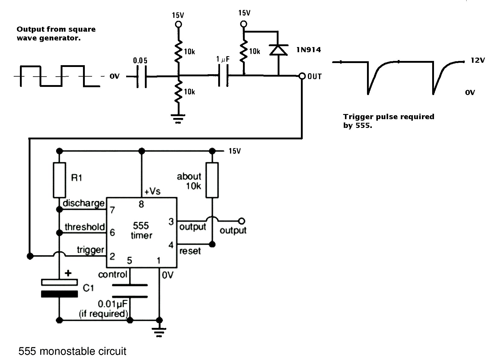
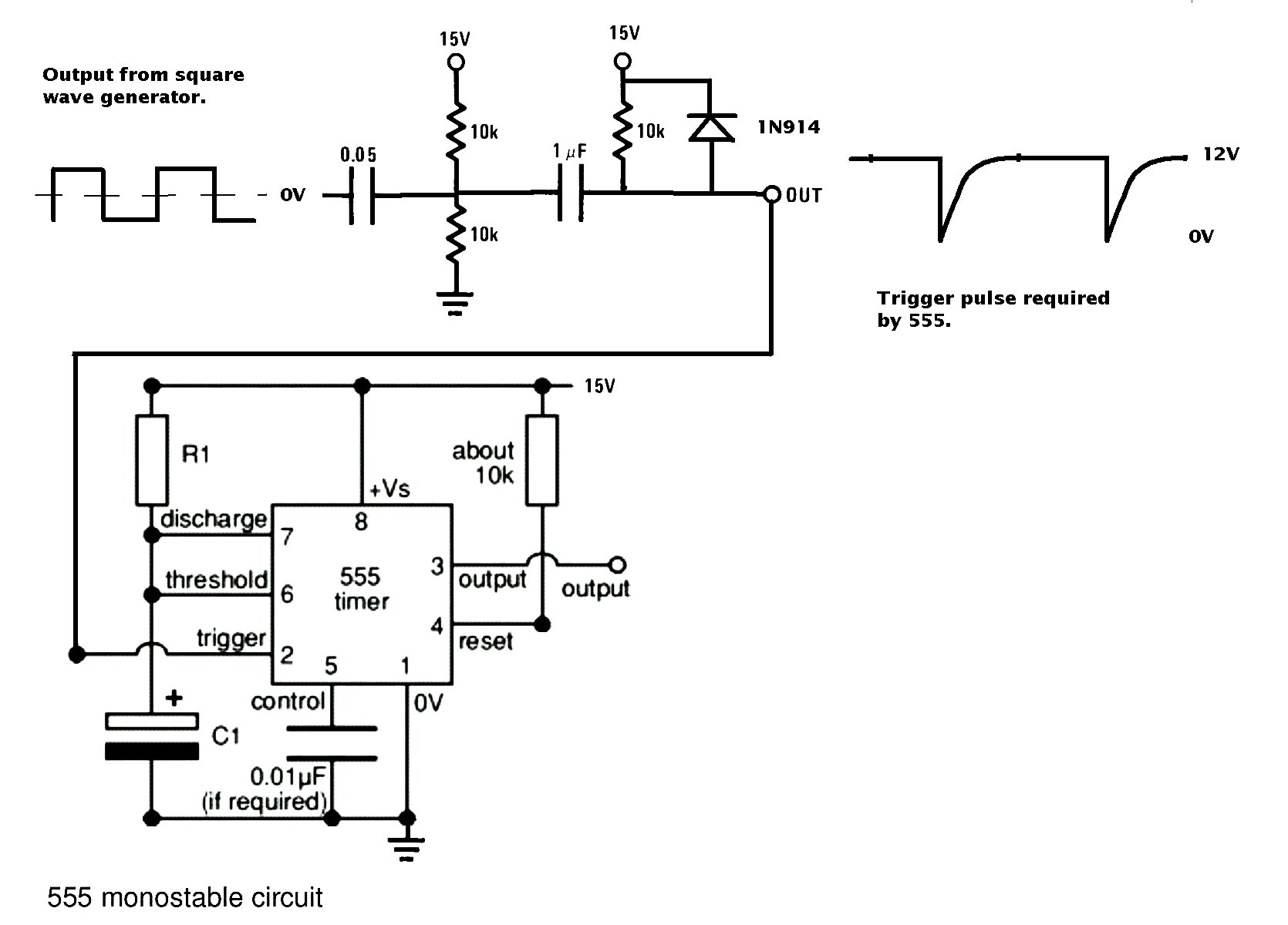
I had to make a change to my schematic for the crank angle
simulator to widen the trigger pulse. The original would not
trigger the 555 reliably. Here is the new schematic. The input
cap was changed from .005 uf to .05 uf
--
Paul Lamar ...No rotor no motor.
Paul,
This is good stuff. I never would have imagined that my questions would
trigger this discussion. I like the idea of an electronic analog system
versus one that is entirely dependant on software. Thanks
Joe Berki
Limo EZ
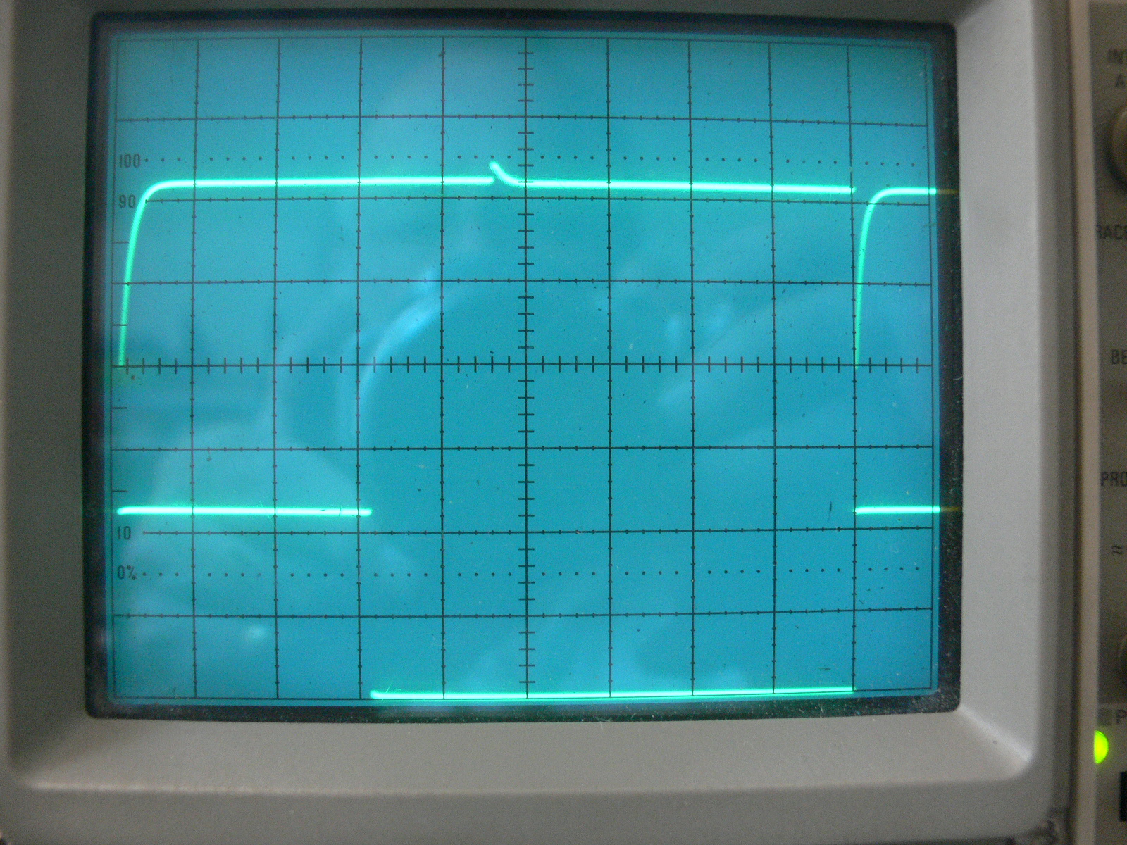
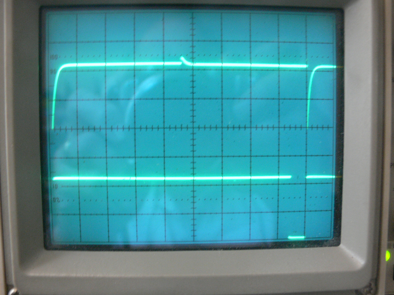
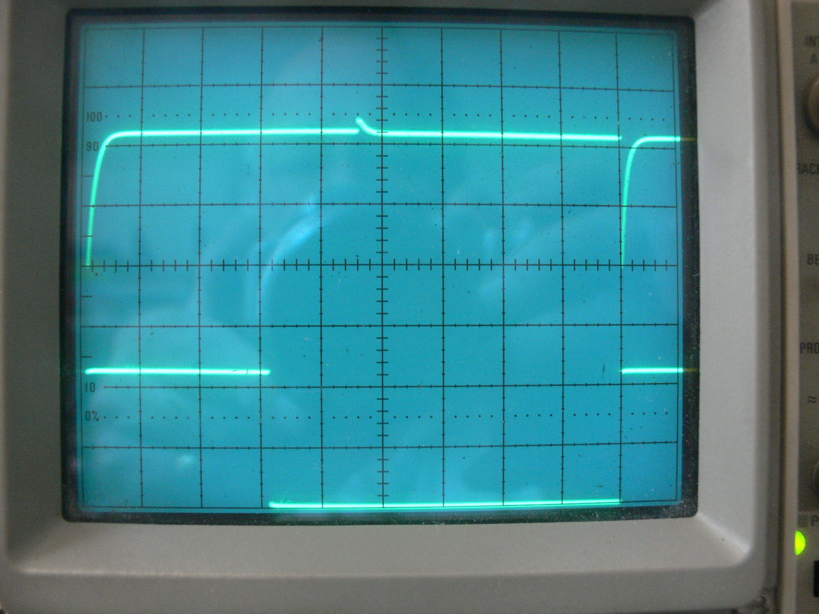
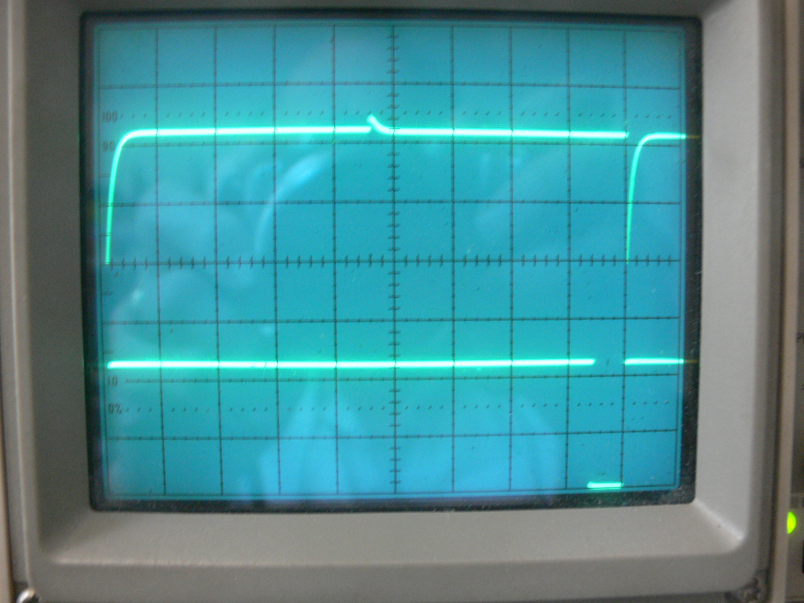
I put a pot in the circuit where R1 is to see what pules width range I could get
at 6000 RPM out of the 555. The scope is set to 1 ms per division.
It went from well below 1 ms pulse width to 9.5 ms pulse width.
Of course the engine only takes 10 ms to rotate once at 6000 RPM.
Top trace is the crank angle sensor signal and bottom trace is the on signal
for the FET.
The injector takes some time to turn on so 1 ms might not be much fuel.
Something like 3 ms would probably be the lower limit for a reasonable amount
of fuel. So that is what you are seeing on the scope. The dynamic range
of fuel supply is about 10:1 at any given RPM.
Those 555's are tough. I inadvertently shorted pin 6 and 7 to the supply
and the 555 started to stink. I cut the power and burnt my finger
on the 555. I let it cool off and fixed the short. It actually blew out
the pot. I put a new pot and a 330 ohm safety resistor in and turned the
power back on. The buck fifty 555 started working again. AMAZING!!!!
--
Paul Lamar ...No rotor no motor.
The Rotary Engine NewsLetter. Powered by Linux.
ACRE NL web site.
http://www.rotaryeng.net
Youtube key word UTUBPLEASE
Copyright 1998-2008 All world wide rights reserved.