Yes we do. Bob White did it. We need a gain of two.
We will make the gain adjustable for tuning purposes.
Maybe one pot is all we need for leaning. The same pot that
changes the gain. The 20K feed back resistor would become the leaning
pot.
--
Paul Lamar ...No rotor no motor.
Bob, I was looking through my op-amp drawer and I found two dozen
TLC274's Are these about equivalent to the TLC272 ?
--
Paul Lamar ...No rotor no motor.
Hi Paul,
Yes, those are the 4 per package version in a larger package. They'll
work just fine.
On the question of richening the mixture, it is also possible to get
nonlinear gain from the op amp by playing around with the feedback loop
if that's found to be necessary down the line.
Bob W.
Thanks Bob.
What would a non inverting version look like?
--
Paul Lamar ...No rotor no motor.
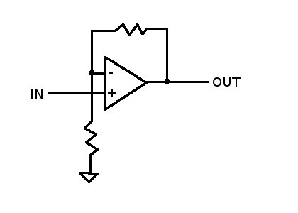
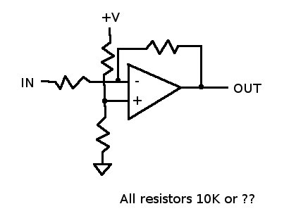
I've attached a sketch of a basic non-inverting op-amp. I would have
to think about the resistor values a bit, and I'm just about to head
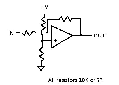
out the door. Another option would be to use one of the extra stages
as an unity gain inverting op-amp. Sketch attached.
In earlier email, you said the gain was 2. The circuit I drew has a
gain of 2.4 (and the actual bias voltage should have been 3.5V, but I
zeners don't seem to come in that value). To set the gain at 2 for
zero V to 10V output range, change the input resistor to 10K, and set
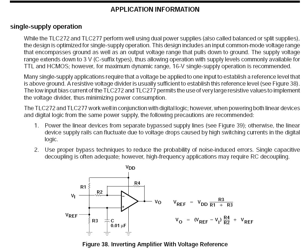
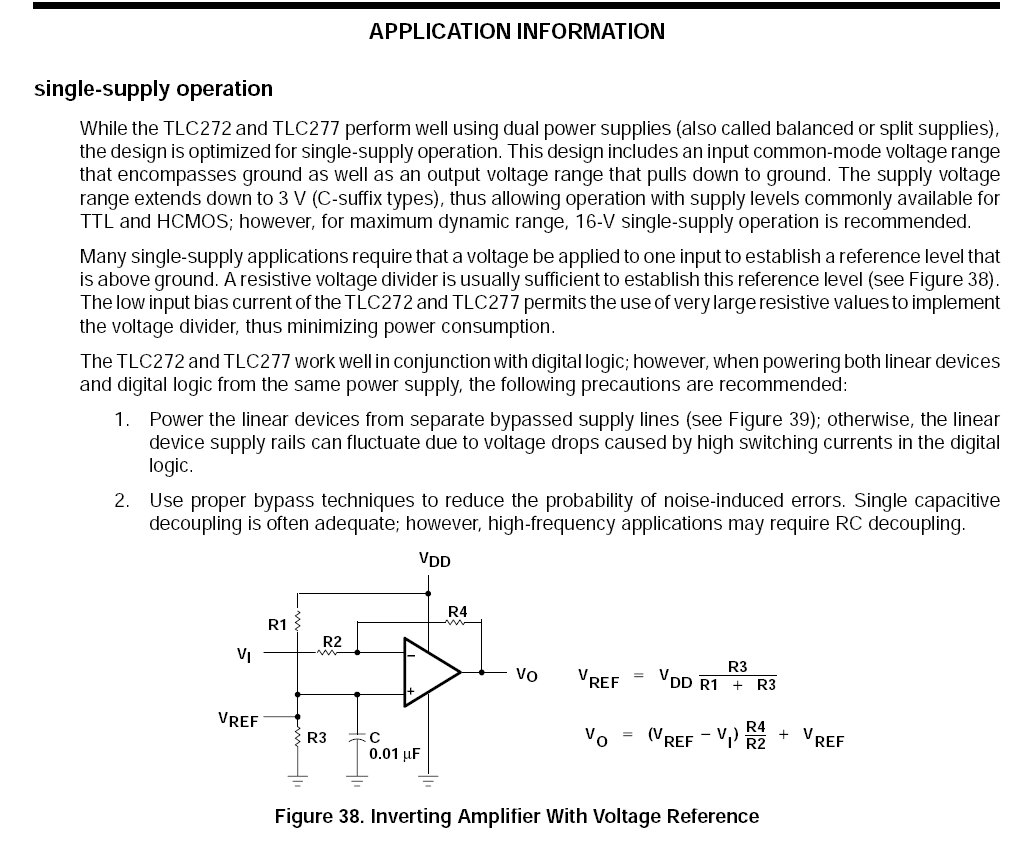
the bias at 3.3. I've also attached a small portion of the TLC272 data
sheet. The whole thing is 47 pages and can be found by Googling
"TLC272 op amp". Changing the feedback resistor to change the gain
needs to be looked at a little more closely to see what happens with
respect to the fixed reference voltage.
Bob W.
The non inverter worked perfectly with 10K resistors Bob.
Exact gain of two.
Next step is leaning by changing the gain. I think a voltage divider
pot on the out put should work fine. Set it up for higher gain
and use the pot to reduce the voltage applied to the 555.
--
Paul Lamar ...No rotor no motor.
The Rotary Engine NewsLetter. Powered by Linux.
ACRE NL web site.
http://www.rotaryeng.net
Youtube key word UTUBPLEASE
Copyright 1998-2008 All world wide rights reserved.