Paul,
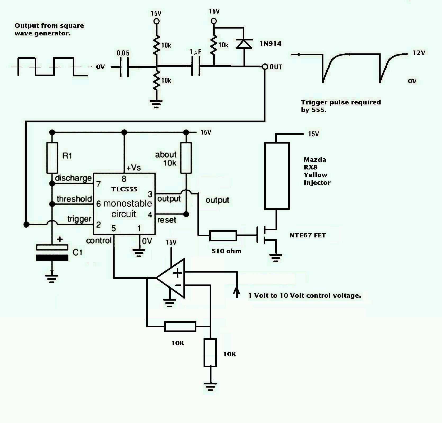
Do you have a schematic for the Op AMp circuit? What kind of gain are
you looking for?
Joe Berki
Limo EZ
Yes we do. Bob White did it. We need a gain of two.
The 555 pulse varies from 1 msec to 9.5 msec
while the mass airflow sensor puts out 0 to 5 volts.
We will make the gain adjustable for tuning purposes.
Maybe one pot is all we need for leaning. The same pot that
changes the gain. The 20K feed back resistor would become the leaning
pot.
--
Paul Lamar ...No rotor no motor.
Bob, I was looking through my op-amp drawer and I found two dozen
TLC274's Are these about equivalent to the TLC272 ?
--
Paul Lamar ...No rotor no motor.
Hi Paul,
Yes, those are the 4 per package version in a larger package. They'll
work just fine.
On the question of richening the mixture, it is also possible to get
nonlinear gain from the op amp by playing around with the feedback loop
if that's found to be necessary down the line.
Bob W.
Thanks Bob.
What would a non inverting version look like?
--
Paul Lamar ...No rotor no motor.
You basicly switch your input and feedback circuits, and the
ground/reference circuit pins. One input is labled (+), and one (-) the
(+) is the non inverting input, and (-) inverting input.
Craig Smith
What is the theory on the use of the Zener diode?
--
Paul Lamar ...No rotor no motor.
Not having the specific schematic in front of me, I'm guessing it is
used as a specific voltage reference? clamping offset current? In
instrument applications, there is usually a pot associated with the
referenced pin for tuning zero, or a zener diode would have the effect
of an offset voltage level.
try
http://en.wikipedia.org/wiki/Operational_amplifier_applications
For some better explanations and references.
Craig Smith
I hooked the current op amp non inverting circuit to the 555 circuit and
what really stunned me is it worked perfectly, including clicking the
injector, all the way from 12 volts down to a 5 volts supply.
If the mass air flow sensor is putting out the same voltage the mixture
would get richer as the 12 volts supply faded.
The FET driving the injector stops triggering around five volts input.
The only problem I can see is the five volt regulator in the mass airflow
sensor would shut off around 7 volts.
You could not say this about a computer system. The five volt
regulators would give up around seven volts.
In theory you could back up this EFI system with six D cell batteries.
------------------------------------------------------------------------
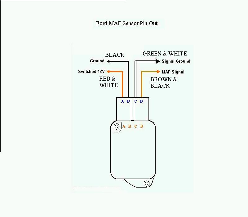
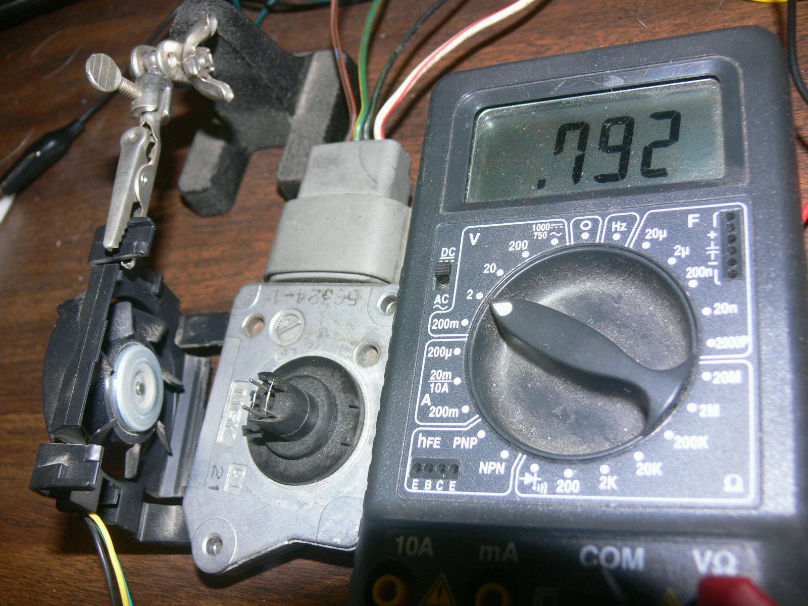
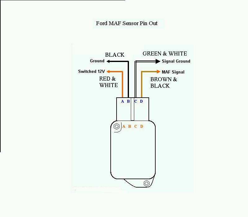
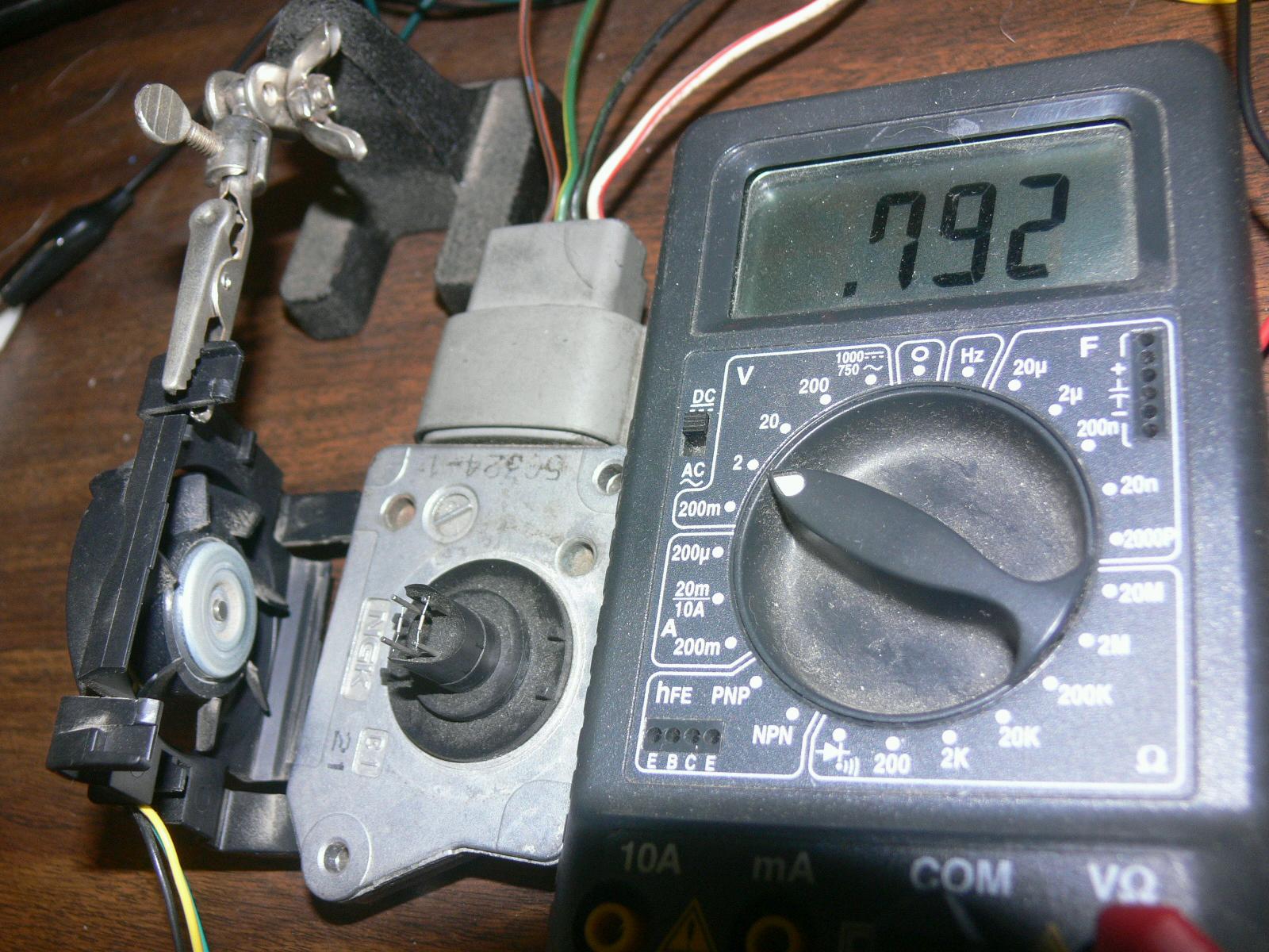
I set up the Ford Mass Airflow sensor (actually NGK) with fan
on the bench.
You wet your finger and put it on the hot wire and the voltage
goes up. Turn off the fan and the voltage goes down.
Works like a charm.
It really is a hot wire. You put
your finger on it without spit and it will burn your finger.
There is a huge power supply filter capacitor in there as after
you shut the power off it takes a long time for the output
voltage to die down. Of course I am not loading the output.
The next step is get some dry ice or speed up the airflow
to test at higher air velocities. Pretty easy to hold it out
of the RX8 car window when doing 140 MPH :)
One way of leaning the mixture is put the mass air flow sensor output
on top of a 1 meg pot and connect the wiper to the op amp. The 555 will
think it is getting a lot less air than it really is and put out
less fuel.
--
Paul Lamar ...No rotor no motor.
The Rotary Engine NewsLetter. Powered by Linux.
ACRE NL web site.
http://www.rotaryeng.net
Youtube key word UTUBPLEASE
Copyright 1998-2008 All world wide rights reserved.