Paul,
I have supplied an attachment, which I have developed for my own use,
it's not perfect as there are variations in different motors, however I
was wondering if it was of any benefit for others.
George (down under)
George,
Good on ya mate. I was just considering doing something similar in EXCEL
but visually your graph is easier to comprehend. I assume P-ports here
and 6,000 rpms. For every rpm you need another graph.
Cheers
Doug
Thanks Doug,
See any major errors - mind you it's rounded to the nearest 10 deg and
designed to orientate visually. I should have done this years ago.
Anyhow it's work in progress and here's an update, mind you it does look
better in Autocad.
Yes, I'm concentrating on 6,000 rpm but the events are the same but as you
say the speed is different for injection and spark. Mind you I don't know
what the timing for spark is for 6,000 rpm so I put in the static timing
marks - again just for orientation.
If you can follow this for cruise 6,000 rpm you can work out other RPM.
It would look better as a continuous line but the numbers diminish in
size -
this way I get most of it on one page.
I also did it for 2 rotors, just to visually see what was happening
simultaneously.
George (down under)
George,
I've look at your chart more than a the first glance and I noticed that
your timing seems to contradict what Paul has stated. Namely the intake
port is open 270 degrees. I guess we have to define 'open' partial
or fully open and closed. Your graph shows that the a leading apex
seal (call it B seal) arrives at a the same location (IO) 360 degrees
after 'A' apex seal passed this location. Is this correct? If the
statement, "The rotor rotates at 1/3 rate as the e-shaft" then the
time and rpm must correlate to 10ms at 6000 rpm.
Doug in Japan.
Doug,
You are correct, it doesn't contradict Paul statement but it clearly shows
the rotor progressing the 80 deg opening stage, from start to fully open.
These readings were taken from a motor with a large degree wheel attached,
so the readings are physically the s-shaft rotation of the engine ( to the
nearest 10 deg) .
The argument is whether there is any real value in this partial open port
shared with the preceding rotor face. I'm open to suggestions on that
matter- perhaps the value is minimal - at best. For this reason I have left
the 360 deg from fully open to fully closed - as I believe this is what Paul
was saying- I did ask him to confirm this but he may be busy.
However if someone argued the value is of significant value, the open port
provides more than 360 deg of intake, more like 440 deg. = perhaps this is
where the 120% VE comes from?
This is where the graph comes into it's own as it provides a clear visual
reference to these events.
The attached graph is not the latest, as I have found a couple of errors in
the maths which I am fixing, but it should more clearly show the
360 deg we are discussing.
George ( down under)
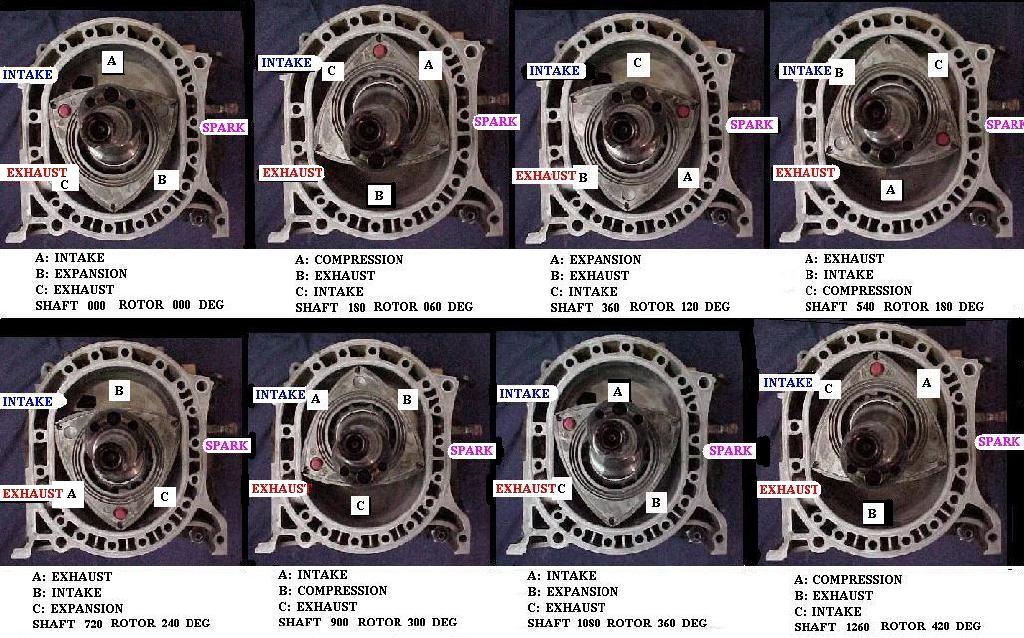
The port never fully closes. It is confusing to talk about it in this
way. Figure from when the apex seal passes the lower edge of the p-port until
the next seal passes the lower edge of the p-port. Note the position of the
eccentric in this sequence of photos.
Paul Lamar
Paul,
Yes it is a little confusing to talk about it. Thanks for the pictures.
I believe George`s graphical information is helpful and I can look at
the area of time I am interested in. I would suggest editing it so it
only shows 360 degrees of e-shaft rotation but this is not mandatory.
Before we determine where the apex starting point is, we have to define
what part of the cycle we are most interested in seeing.
It should be noted for everyone that George and I are speaking about two
totally different places of fuel injection. Perhaps we should be on
separate threads. George is concerned with manifold air speed and how
that affects the transfer of fuel from the manifold injection point, to
its arrival into the Intake area labeled 'A' in the first photo of
How-wank-works, jpeg Paul posted.
I am only interested in what happens in the chamber space between apex
seals as depicted by 'C' in the second picture in the series. Lets
consider that my injectors are placed about where the label 'INTAKE'
is shown, then you can understand that I would want the fuel to start
injecting into this area 'C' about this rotor position.
Now look at the third picture in the series and note that the injector
could still be injecting well past this position before the following
apex seal closes the intake port and immediately afterwards the fuel
injection port. Also note that Mazda new research engines with the
hydrogen injector at 12`clock position probably injects at this time as
well. Again mixing a wee bit of hydrogen with the other hydrocarbon
based fuels increases the flame front speed.
Why am I trying this injector location? I am trying to test a theory
that spraying fuel directly into the housing intake chamber will help
improve fuel burn efficiency. Mazda research engines appear to be going
this way and they are economy and emission driven of course. This is
not direct injection in the normal use of the phrase, as that would be
injecting on the compression side of the stroke.
Housing intake chamber injection supposes that, by delaying the injection
of fuel until the exhaust port closes, we may save some fuel from going
down the exhaust port. My second reason is probably the influence of
too many years designing for Japanese clients. That philosophy states
that if an idea is reduced to its minimal size and simplicity its
functionality will increase and surrounding components can also be
reduced in size. Usually the merits are not immediately apparent.
Several questions remain. How much heat will the rotor lose when fuel is
contacted with it?
Is cooling the rotor by spraying it with fuel a good thing?
How to mount the injector tubes? I am open for all opinions here..
I have done a design using a 15.1mm ID stainless pipe that will have an
O-ring seal on the inner housing and a taper NPT thread on the outer
part. This would screw into the outer housing sending the pipe into a
bored step in the inner housing. Obviously the hole is being drilled
fairly perpendicular to the inner housing. The challenge is sealing on
the outer housing. It is not flat in this area and sealing with Teflon
thread putty would be marginal.
I therefore have purchased the 2nd generation alloy aluminum brazing rods
from an outfit named Technology Products in Florida. These rods still
require the welded area to be 200 degrees below melting point of the
housing metal however. Heat dissipates rapidly in the housings so that
also means a lot of heat has to applied into them to bring the welded
area up to at least 550 degrees. I am concerned the housings might get
deformed.
Has anyone done any welding on the rotor housings and then run them or at
least 'mic' them to see if they are still true? I don`t consider TIG
welding on the inner liner to be a problem because it so precise and
localized. I want to build up the aluminum housing thickness around the
injector mounts before drilling and tapping and hence my concern. Ditto
on the P-port intakes, with the same technique and same concerns.
Doug in Japan
The Rotary Engine NewsLetter. Powered by Linux.
ACRE NL web site.
http://www.rotaryeng.net
Youtube key word UTUBPLEASE
Copyright 1998-2008 All world wide rights reserved.