Hey all,
Came across this reading up on the rx7club.com and rx8club.com website.
Here is the link. This is exactly what I want to do with my car but with
lightweight housings. It would put me at the power and weight level I
would need for my platform. I am sure Paul will rave about doing a
P-Port which would make life easier in the long run and I will consider
it when I feel it there is supporting data to back the claim. (Note: Not
trying to be mean Paul just stating what I did before because I know
what your response would be.) Its worth getting on and seeing some of
the conversation. It brings up an important question I had about port
balance and the engine. I know why they have different
shape/flow/timing ports but for a performance automotive aspect and for
that matter a constant rpm aerospace aspect such as your it would seem
to me that you would want a symmetric port configuration. OEM
driveability seems to be of little use to us even if we have different
platforms to put them in. I I am going to port a lengthy response to the
incredible information that Steve posted two days ago and this will be
part of the reference to what I am talking about. Just though you guys
would like to see a working, proven setup even though it is still in its
tuning stage. I heard 260lbs bare block for a 20B. Lightweight housings
should put this at about 210. With all accessories and such we can say
300lbs would be reasonable foe a N/A three rotor with I imagine around
375hp and 225 ft-lbs. For you plane guys as long as you could fit the
length then it would be a wash with a two rotor turbo weight wise and
you would have better reliability over a turbo setup and with less cost.
http://www.rx8club.com/showthread.php?t=141000
http://www.youtube.com/watch?v=JZLFUCqdMZ4
http://www.youtube.com/watch?v=40Hohpsjq2E
Rob Woods
585-615-8474
That engine would be lucky to see 300 HP :)
Paul Lamar ...No rotor no motor.
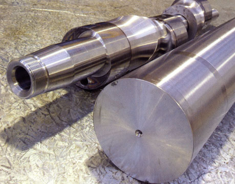
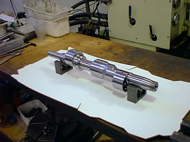
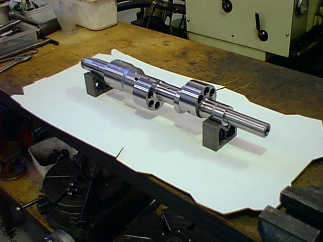
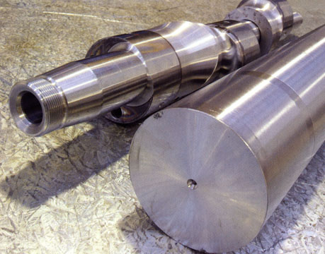
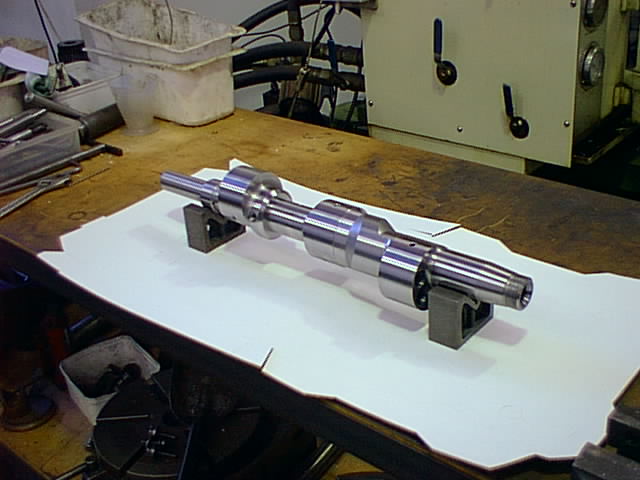
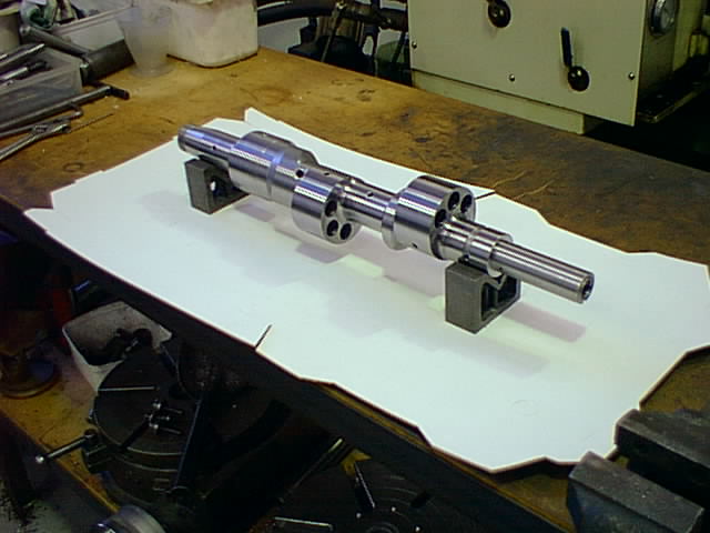
So I assume this engine would have to have a custom eccentric shaft, as it
doesn't have the thick center housing of the factory 20B. It would be
interesting to see a picture of the shaft.
Larry
Larry,
The guy who did the engine isnt really forthcoming because the people
on the message board did stupid messageboard things and I think he got
gunshy about putting info out due to being hasseled. I am going to email
him soon to ask some legitimate questions and that was on my list so
hopefully I can get some out of him.
If I did the shaft I would do a three piece shaft. The first piece would
be the shaft and the lobe for the center lobe. The second and thrid
piece would slide onto the ends of the shaft. By doing this you can get
a bearing, journal or anti-friction, on either side of a lobe to make
one hell of a rigid setup. Also I never really liked that tapered
section and keystock method. That really doesnt induce much rigidity
into the shaft assembly because you are not engaging the slider lob as
much as possible. I dont have one in front of me to see if there is room
to do a full length taper but I do know that taper fits work best in
terms of assembled stiffness when you engage as much as possible. I
would even go as far as use a taper 3 lobe stoffel spline and toss the
key all together in order to increase the center lob shaft thickness. I
used stoffel splines on my formula car and they work great. Neat thing
is with a 3 lobe spline you could orientate the lobes to make a even
fire 3 rotor or a "big-bang" 3 rotor. Now that would be interesting to
test. As far as the centerplates and bearings are concerned I sent a pic
of that stationary gear 2 weeks ago that showed the modified stationary
gear in the plate. Do that for the first plate and for the second plate
do the same but just cut the gear off. Then you would have a journal
bearing on each side of each lobe.
Rob Woods
The bottom of the eccentric lobe is the same as one side of the shaft.
If you make a 3D dwg of the Stoffel arrangement that will become apparent.
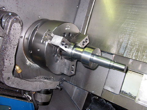
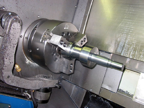
I think these are pictures of the Guru 3 rotor shaft using the thin center housing.
Stoffel splines are unnecessary. A taper and a key way with a long tension bolt
holding them together works. Stoffel splines are expensive to machine.
http://stoffelpolygon.thomaswebs.net/ They also allow sliding in and out which
is not what one wants in this application.
Paul Lamar
The Rotary Engine NewsLetter. Powered by Linux.
ACRE NL web site.
http://www.rotaryeng.net
Youtube key word UTUBPLEASE
Copyright 1998-2008 All world wide rights reserved.