Lynn,
Thanks a heap. I share your design philosophy. Yes on both side by
side
injector inserts and P-port inserts, I was planning to groove on the
insert sleeve circumference itself in two locations. Yes direct
screw-in inserts can be problematic because NPT threads are difficult to
position exactly, and if the insert bottoms out on the inner liner it
could cause a small distortion or interfere with flex charteristics.
The DEKA IV injectors are only 15mm in diameter so I can slip a 19mm OD
tube in fairly easily with room to spare to seal the outer part. The
back side of the inner liner will be drilled and the hole tapered to an
angle slightly narrower than the injector tip profile. I can bring
the injector tapered tip to about 0.5mm from the inner housing but
probalbly will back it off to 0.7mm.
Thanks for confirming my concerns with welding. Obviously you have
'Been there done that' so I appreciate your experience. About TIG
welding the intake P-Port tube. Are you concerned with localized
embrittlement? I know the chromium in stainless metals tends to migrate
when TIG is used.
Doug Fir
/I would not be at all comfortable welding on the sealing surface. There
is no getting around/
/the shrinkage that occurs when a weld bead cools. If no cracks appear
then the weld bead must/
/stretch a bit and some stress will remain in the parent material. It
is not a requirement for /
/manufacturing a Pport. I used exhaust pipe tubing on my first set of
housings and it worked fine. /
/I just filled the housing void with Devcon Plastic Aluminum. Worked
fine power wise. The fellow who /
/I built it for let it sit for three years before installing it in a
Mini Cooper. He ran/
/three Autocross passes with not enough water and no oil pressure.
Chrome came off next to the /
/inlet tube. Among other problems. If I were doing it again, I would use
a thick walled aluminum/
/tube with a light press fit on the inner wall to help support the
housing when the stack is torqued up./
/No evidence that high temps bothered the epoxy. I used to grind the
sides off of Go Kart engines./
/Make bypass ports of modeling clay and cast Devcon over the mess with
cardboard dams./
/Rinse the clay out in the cleaning tank, and have the slickest side
ports in racing. Never had /
/Devcon come off. /
I understand your outer 0-ring cap design so no need for a drawing.
That would work if the housing area around the injector tube location
was flat. Unfortuantly it is not. My choice location for the fuel
injectors is to place them on each side of the oil injector hole. One
challenge - that area angles inward towards the center of the housing.
About 4mm or "8/32". I would have to fill it in or mill out the high
spot for a diameter of at least 30mm around the center of the insert.
Neither solution appears doable for various reasons.
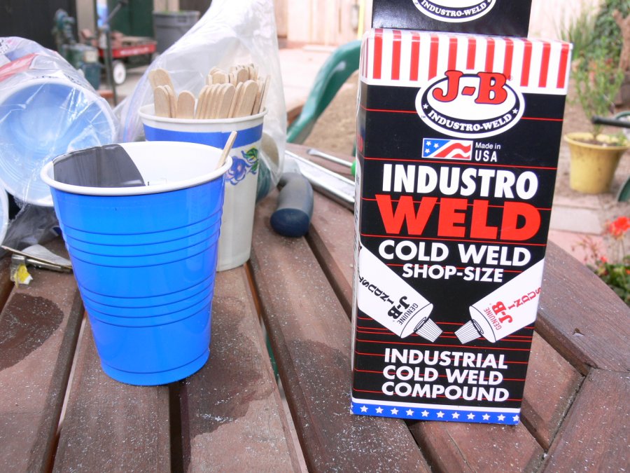
No I haven't considered JB Weld, and won't:) I had originally intended
to screw in a one inch long male threaded tube with a smooth bore ID of
19.1mm. The 19mm sleeve with its reamed 15.1mm ID would have grooved
O-rings top and bottom, that contact both the inner housing step bore
sides and the inner dimension of the outer housing threaded tube. Two
4mm set screws 90 degrees apart around the circumference (4mm could
lock the sleeve to the outer screwed in pipe..
One trick I learned over here is to insert the sleeve, tighten the set
screw until it bites into the inner sleeve. Loosen the screws, take out
the sleeve and just drill the marked area a tiny bit creating a
concave point. Install sleeve again and tighten the set screws. The
sleeve is not going to move in any direction
/With a fat "O" ring there would be no need for the collar to even touch/
/the injector tube. Just two socket heads to hold the collar in place in/
/ the longitudinal line and 2 or 4 set screws as you describe. A chamfer /
/around the hole for the fat "O" ring and no further machining would be /
/required. /
Great news on the fuel behavior. Bad news on having to inject through
the top:(
I was hoping I could get away with adding oil to the fuel, but
like you
said it may be vaporized and become fuel before it acts a lubricant.
Doug in Japan
Synthetic oil does not vaporize until over 500 F. Put some in an oven.
Tracy adds oil to the fuel and sometimes if you add too much the
crankcase starts
to fill up. It can't be all burning. The apex seals are oil cooled.
Without
the oil they over heat.
/Synthetic crank case oils don't vaporize readily./
//
/Most synthetic 2 cycle oils lubricate great and burn great, are ash
free and coke free./
/ (Red Line racing 2 cycle for dirt bikes) In my case. Compared to /
/dino based multi grade crankcase oil that looks like the engine was/
/ running on mud. With carbon seals the housings look better the /
/longer they run. the rather dull finish gets shiny like bumper chrome./
/I just sold our ceramic seals to an IT driver. Never ran metal seals./
/I have built engines with them but never my own./
//
/I have been gifted dead rotaries that had nothing at all wrong with them /
/other than being run on multigrade dino oils and the stock OMP./
/Sludged shut seal grooves and not enough compression to even start. /
//
/Way too many good looking Mazdas have gone to the shredder for /
/no good reason./
//
/Lynn E. Hanover/
With 4,500 hits on youtube I have had no negative feedback yet on the
welded p-ports. One would think someone has built one somewhere
beside myself. Since there is a chamfer around the opening if the
chrome comes off it is nothing to do with the tig weld. It would
come off with aluminum p-ports as well. Since there is no pressure across
the port sealing in that area is not an issue. If heat is going to affect
the adhesion of the chrome you would see it on the exhaust port area.
When the exhaust ports first open there is a supersonic jet of extremely
hot gases at high pressure shooting through the slot. That is one
reason the apex seal runs so hot.
The P-port RX8 engine is coming back from Mazdatrix and going on my prop dyno.
Paul Lamar ...No rotor no motor.
Lynn,
Thanks for the info on syn. oils. Next. You mentioned:
"With a fat "O" ring there would be no need for the collar to even
touch
the injector tube. Just two socket heads to hold the collar in place in
the longitudinal line and 2 or 4 set screws as you describe. A chamfer
around the hole for the fat "O" ring and no further machining would be
required."
Yes I understand. The O-ring deforms and is pressed into the injector
tube. This is
exactly how we seal glass tube against water pressure in our UV
sterializing equipment except the collar can be screwed on to the
intermediate fitting.
In the engine case, the collar 0D would have be about 27 to 30 mm to be
able to comfortably accomodate the two retaining longitidual screws and
avoid hitting the fat O-ring. To flatten out the housing area in
question, are you advocating filling the depression in the central part
of the housing with Devcon aluminum epoxy? If so, I would then mill
it flat, and bore a 45 degree chamber into the combined epoxy, and
aluminum housing. This then would be asking the interface bond between
the epoxy and aluminum to become a water barrier, as well as a
structural support for the fat O-ring in close to half the
circumference. The water barrier ability of the epoxy is an unknown for
me.
Doug in Japan.
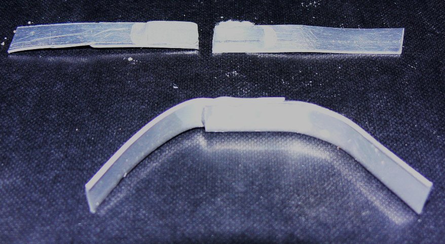
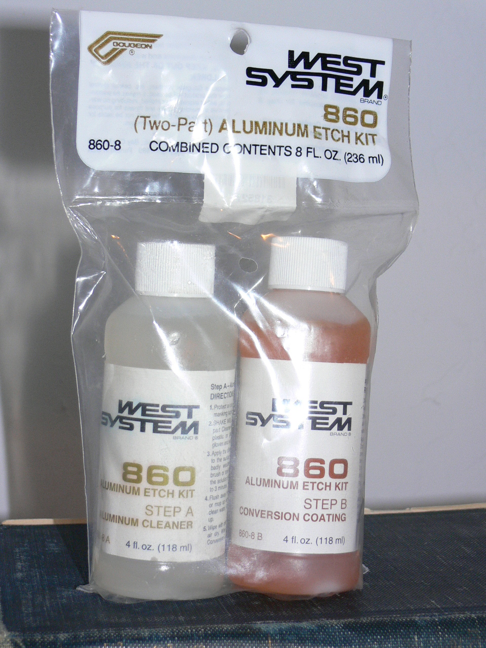
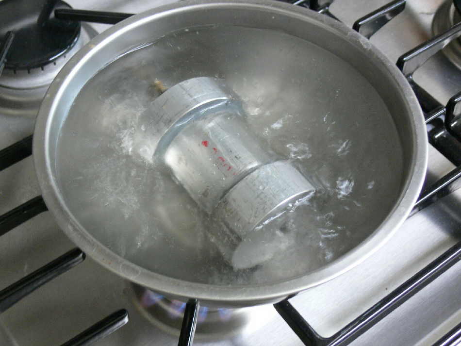
What ever kind of epoxy filler you use the secret is the preparation of
the aluminum. You need to get a kit from a boat place for that purpose.
If you prep it correctly any filled epoxy will work great. If not
it won't. We did extensive hot and cold pressure testing.
Paul Lamar
The Rotary Engine NewsLetter. Powered by Linux.
ACRE NL web site.
http://www.rotaryeng.net
Youtube key word UTUBPLEASE
Copyright 1998-2008 All world wide rights reserved.