>>> Hi Paul,
>>> Are the Hatch exhaust ports available anywhere or must one fab his
own?
>>> Also, is anyone building and selling an aluminum oil pan for the 20B
>>> engines? I thought maybe Ed Klepeis was but I dont know how to reach
>>> him. Can you help me contact him? Thanks much!!
>>> John Bell
>>>
>>>
>>> Hey Steve Beckham, do you want to build and sell those exhaust
flanges?
>>>
>>> Jerry Hey at
jerry@jerryhey.com <mailto:jerry@jerryhey.com> can
build a 20B oil pan.
>>>
>>> Paul Lamar
>>
>>
>> Paul, you ask about possibly making and selling the ports/exhaust >>
flanges.
>> We hope to do this with a refined design to make them more
affordable and
>> easier to build. If the vendors cannot be found who can make them
>> affordably, we'll simply make those drawings available through you.
>> Apologize for the length of this response but there are a lot of
factors >> in
>> play. Following are some.
>>
>> Phillip Groelz, Francis Romig and Chuck Smith are contributing to
>> development work on various engine components with an eye on
possibly >> Chuck
>> providing these and other components, including complete engines
sometime >> in
>> the future. But if this happens it will not be in the short term. The
>> exhaust is a good example.
>>
>> We'll have to come up with a more cost-effective way to make the single
>> piece that is a combined port insert/four stud flange/and pipe >>
attachment.
>> When Everett, Francis and I did the prototype integral ball joint
>> swivel/flange and port insert, it was a test of the basic approach. It
>> worked well but as with any first piece had areas that needed
refinement.
>> And we spent way too much time building the damned things. Francis
>> fabricated the dies to stamp the female part of the swivels and
machined >> the
>> male part of the ball joint from SS 321 stock. After machining, this
>> male
>> portion of the ball joint was welded to the flange. The port insert was
>> welded to the flange from the inside and the insert wall built up to
>> properly transition from the insert to the relatively small exit
diameter >> at
>> the flange. The interior weld-up on the port insert was necessary for
>> transitioning from the port insert to the flange because we used >>
relatively
>> small diameter exhaust ports and pipes and the matching male/female
joint
>> pieces sized accordingly. The male portion of the ball joint was welded
>> from both the inside and the outside using a machined recess.
Following >> all
>> that welding, the back side of the flange was again machined flat. When
>> finished, it produced a solid, single part . With good welds, there was
>> nothing to break or leak and nothing cantilevered off the flange.
The >> port
>> insert, flange and the male portion of the ball joint were all >>
registered
>> and held in place by the four studs and washers/nuts. But many, many
>> hours
>> of work involved in each.
>>
>> We went to all this trouble with the port insert because we found the
>> effectiveness of the insert helped tremendously with noise reduction
>> while
>> lessening the demands on the muffler and keeping it light. The
relatively
>> small back pressure penalty associated with the port insert was >>
considered
>> well worth it. The SAE paper that documents Mazda's findings when they
>> finalized the port insert show that little insert is very effective at
>> reducing exhaust noise and well designed. The same mufflers we were
>> using
>> for dyno and flight tests immediately worked much better and lasted
much
>> longer with the port inserts installed. And no more numb feet from
off >> the
>> concrete slab where the dyno stood and also helped eliminate loose
rivets >> on
>> the bottom of the fuselage during flight tests.
>>
>> The revised design needs to avoid the adjustment/preloading hassles
>> relating
>> to the ball and socket. I was always having to adjust the preload. We
>> tried springs for this but with them right at the port, we just
could not
>> figure out how to make them work with repeated cycles of up to 3.5
to >> four
>> hour flight legs at WOT. And there was no sort of redundant safety
>> feature.
>> A major safety concern. It may have been that we should have used >>
different
>> materails for the capture plate on the outside of the socket. But this
>> experience is what led us to what you see in your photos with the outer
>> female capturing flange held on by four 12 point high temp nuts.
>>
>> We hope to work to test some configurations that refine the concept
to >> where
>> we can come up with something shown in tests to be safe and proven.
>> Retaining the ball/socket arrangement right at the port is my
preferable
>> choice. So far unable to locate any commericially available exhaust
ball
>> and socket assemblies that are of the correct design, robust material
>> (Inconel preferably), the right sized pipe and light weight. A >>
complicating
>> factor is the design needs to incorporate provision for a nice tight
>> radius
>> right out of the port for tight cowlings on single or tandem seat >>
aircraft
>> (worst case scenario). You can see in your previously distributed
photos >> of
>> our protype set that they worked very well in that regard in both
the >> RV-3
>> and RV-4 where we had engine mount tubes located in the vicinity and
the
>> cowling a coupleof inches from the ports. Space wise, no big deal for a
>> side-by side aircraft --except we found that cantilevering any heavy
>> components (i.e. mufflers) out to the side, ultimately proved to be
>> problematic. So we simply kept everything in as close to the engine and
>> centerline as possible and this helped with both structural and space
>> considerations. The ball joint eliminated the stress and cracking of
>> pipe,
>> weld and flange while using relatively thin, light weight components
>> throughout. And it concurrently eliminated the expansion/contraction
>> stresses and related cracking in that area as well.
>>
>> The followup design we are currently building for dyno and flight
testing >> is
>> slightly different than the prototype shown in your photos. We are
using
>> two prototype Inconel ball sockets an experienced aerospace
fabricator >> did
>> to spec for us to test. These ball joint swivels are located
immediately
>> following the short bend out of the port. Hopefully that short lever
>> from
>> the port to the ball joint will not stress the pipe/flange
intersection >> due
>> to the combination of factors including the ball joint and the short
>> lever.
>> And the ball swivels are a pratical help as well by providing some
>> lattitute
>> in pipe location. The Inconel material cost alone makes cost
containment >> a
>> challenge. But safety is a paramount concern with these components.
If >> we
>> can make something like this work, we can try it out of thicker
section >> 321
>> and see how that holds up. If those two Inconel units test well, and we
>> can get him to produce them, that may be a good first step.
>>
>> Meanwhile, the plan is to get the first engine fully integrated with
the
>> airframe, including exhaust, heat exchangers, baffling, plumbing and
fuel
>> system completely installed. Then will take it out of the airframe
and >> do
>> dyno testing and tuning with the reduction gear and test club
installed.
>> Depending on what kind of numbers we get from those tests, we may
>> disassemble the engine and install a second set of rotor housings with
>> larger diameter port inserts, throttles, intake runners and a different
>> configuration plenum then put it back on the dyno to get more
numbers. >> The
>> first engine for testing uses fairly small diameter ports, throttles
and
>> induction tubes. The power section of the engine is assembled and
ready >> to
>> install in to the aircraft but we need to do some work in the fuselage
>> including installation of Don Rivera's dual electric fuel pumps/filter/
>> relief valve package and fuel selector (duplex valve for automatic
>> return
>> line switching when tanks selection is made). The aircraft was on
the >> gear
>> with wings installed but we took all that off and put the fuselage on a
>> rotisserie to rotate it so that old men with bad backs can more easily
>> install all the fuel and electrics. That done, we'll put it back on the
>> gear and install the engine and reduction gear and then finish the
>> exhaust,
>> etc. When done there, the engine will come off and go on the dyno.
>>
>> Following that program, the plan is to then conduct some extended
flight
>> tests to see what kind of numbers it produces and if everything
holds up.
>> If all of that is to satisfaction, we'll see about offering various
>> components, complete fuel injection system and/or components, possibly
>> through Don Rivera at AirFlow Performance. And Chuck Smith has
indicated
>> interest in producing other components as well as complete engines with
>> reduction gear. We'll test that prototype reduction gear on the dyno
and
>> RV-3 as well.
>>
>> Regardless of what transpires ultimately, if we can't get vendors
who >> will
>> produce the exhaust tooling and finished parts, we'll simply give
you one
>> for you to make detail drawings for anybody who wants to use them for
>> reference. Apologize for the length of this reply.
>>
>>
>> Steve Beckham
>>
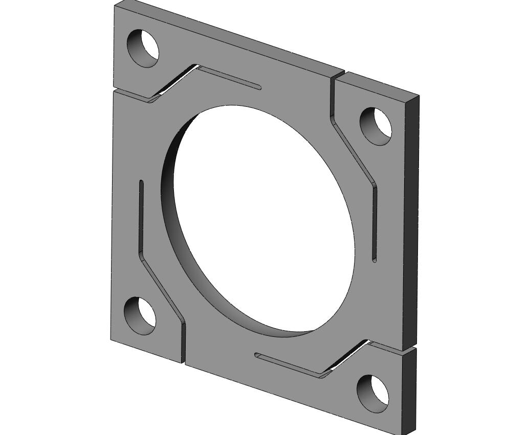
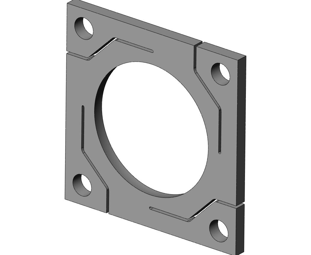
>> Steve, consider offering the Teflon slide throttle. Aircraft engines
>> spend 90%
>> of the time WOT and the slide throttle has no internal aerodynamic
drag >> so the
>> BSFC and power is better. Here are some pictures. It is cheap if
punched >> out on
>> an NC punch. Ten or more holes sets are punched at one time and then
the >> covers
>> are sheared to final size. People have complicated them with oblong
>> holes, NC
>> mills and rounded ends but all that does is increase the cost. Mazda
>> engines are
>> chosen for aircraft because of the lower cost so the idea is to keep
the >> cost down.
>>
>> Paul Lamar
>
> Steve,
> I have discussed the swivel exhaust flange (SEF) with my machinist
> neighbour and between the two of us we came up with almost exactly
the > some
> protocol for making them, i.e machining the inner and outer plates and
> flaring the tube. This makes the outer plate thicker and heavier. Making
> your own dies for the flare isn't a real problem - just use some carbon
> steel and harden it after machining.
>
> I would probably prefer a stamped outer plate but it's more cost for
dies
> for a one off.
>
> I had decided to proceed for my one off and your e-mail was timely,
in > that
> I'm sure it will now work that way.
>
> BTW I would stick to a 2" exhaust pipe, a little bit bigger is better
than > a
> little bit restrictive.
>
> Thanks again for the timely info.
>
> Has anyone spoken to Larry to see if he was interested in doing this
> production - probably right up his alley.
> George ( down under)
Thanks Paul. In your email I did not see the photos attachments you
referenced.
We did draw up a system using a slide throttle arrangement but did not get
around to testing it. Do you use it at the plenum and wet runners or other
configuration? Similar to one of Ben Ellison's throttle body injector
units?
Steve Beckham
We ran them on the dyno and on Mark Supinski Mustang II so far. The
injectors
were placed near the open ends but anywhere will work. The idle was good.
I could not tell the difference compared with the P.S. engine idle. They
all have to idle above about 1800 engine RPM (630 prop RPM) as the gear
box shakes.
Do you have "view attachments inline" turned on in your email program?
Did everybody else get them? Here they are again.
Paul Lamar
Paul and Steve,
here was a thought I had on making a "spring" clamp to hold the ball
flange on uncrushed. The material needs to be a tough enough steel that
it would remain springy. This was a quickie effort, I hope that it is
obvious as to function.
Bill Jepson
--
The Rotary Engine NewsLetter. Powered by Linux.
ACRE NL web site.
http://www.rotaryeng.net
Youtube key word UTUBPLEASE
Copyright 1998-2008 All world wide rights reserved.