Paul,
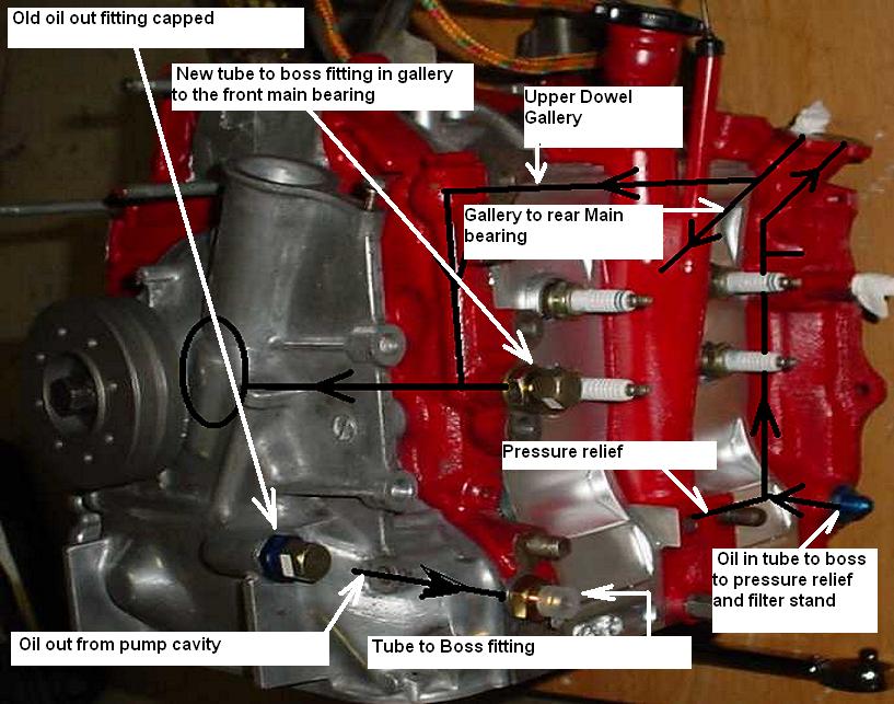
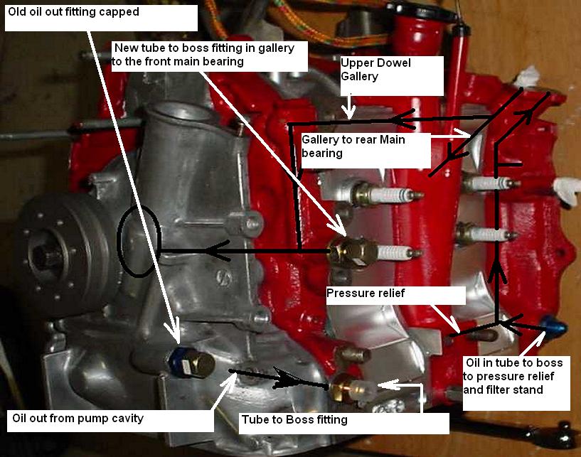
Looking at RB early aircraft engine I noticed the abundance of oil lines.
Functional but many. To be fair this was before the common use of
electric C/S props so there were oil line to and from the prop governor.
In recent posts in the last few days you have posted a picture showing
the location of an additional oil feed source to the front bearing.
For the existing oil filter stand I think perhaps we can just cap it so
the two holes remain connected. Here is why.
Oil could come straight out of the modified oil passage into the oil
coolers, and from there into a remote oil filter mounted on the
firewall. The oil lines will therefore be short because the oil filter
can be mounted on the firewall. The oil filter can also be mounted on a
thick piece of machined aluminum block that can double as a oil
manifold. Hence all of the oil flow is filtered.
From the manifold we need lines to the following inlets:
1. the front bearing
2. the rear bearing (blue anodized fitting) and hence internal flow to
the pressure relief valve.
3. The turbocharger if you have one
4. the gearbox PSRU if you have one.
That is four lines. I am wondering if the lines can be daisy chained
reducing them to two lines? On the plugs side, one line connecting the
two bearing inlets and on to the PSRU necessitating the use of tees at
the junctions. On the exhaust side one line to the turbine.
Doug in Japan
--
The Rotary Engine NewsLetter. Powered by Linux.
ACRE NL web site.
http://www.rotaryeng.net
Youtube key word UTUBPLEASE
Copyright 1998-2008 All world wide rights reserved.