Hi everyone, I'm about to demonstrate more of my ignorance about the
Renesis engine; here goes.
This first picture is of the water pump, which has 6 connectors
(labeled 1-6). Two of them (#1 & 3) appear to be the primary
inlet and
outlet, but what are the rest for?
The second photo shows one more coolant connector (#8), don't know
where it goes. #'s 7 & 9 are sensors; I'm guessing #7 is a knock
sensor, but don't know what 9 is.
I've got the RX-8 service manual on CD, but it's not very user-
friendly when it comes to answering questions like this.
Kenith Arron
The first picture is of the thermostat holder. The top is hot water
out of the block and the bottom part is cold water into the
water pump.
Most people remove this device and build and adapter to achieve
the same functions. In theory what one wants to do is use cowl
flaps to control engine temperature as that reduces cooling
system drag during low power cruise.
Also removing the thermostat allows the water pump to pump more
water with less HP consumed. More water flow improves the heat
transfer from metal to water.
Second picture:
7 is knock sensor.
8 is heater hot water out of the block.
9 is oil pressure sender.
Last picture the answer is yes. A Corvette device also works well.
Shoot for a 30 psi pressure cap.
Paul Lamar
Kenith,
Keep asking these questions, with pictures . . . . it means I don't
have to be the "ignorant" one :))) I can hardly wait to get the answers.
Randy
Thanks for the answers; like any good answer, more questions were raised.
I went online browsing my bookmarked pictures of rotary aircraft, and
noticed the thermostat-housing-replacement-block you describe. I popped
my stock housing off, the concept looks straightforward to fabricate,
but one thing I observed was everyone had substituted some other fitting
for the 1.5" press-on radiator hose fittings. What are those fittings
called, size, etc. I'm using an auto radiator and I'm wondering now if
it's a good idea to use the press-on's it comes with or convert those
too (if possible)? Also, one builder mentioned adding an 'in-line'
thermostat as they were removing the stock one; opinions?
BTW, I finished a trial fit of the lower center mount bracket to the
nose strut channel on my 801, and everything fit together well. The
bracket perfectly captures the bungee pin, and could probably support
the entire engine. I will have to remove the bracket to change the
bungee, but that's livable. You have to pull the engine to change the
bungee anyway.
--Kenny A.
http://websites.expercraft.com/kennya/
One and a half is good. It increases the vlocity of water going through the block.
We went around and around on this a few years ago. The trouble with the large
AN -20 -24 line besides the high cost is it is very stiff. That can lead to
cracks in the thin aluminum rad header tanks. The best compromise is the stuff
they use on over the road tractor trailer trucks. Namely blue silicon hose and
Breeze constant tension hose clamps. You should get my How to Cool Your Wankel
book from Aircraft Spruce or Mazdatrix.
"To give you a feel for the plumbing problem a liquid cooled aircraft cooling
system can run 30 psi relative pressure. If the coolant hose is 1-1/2 inch in
diameter there is a force of 53 pounds trying to pull the hose off the hose
connection hardware. If AN hose and fittings are not used dollar-an-inch high
quality blue silicone rubber hose must be used with constant tension hose clamps
made by the Breeze Co. or equivalent. These are obtainable nation wide from
industrial supply companies such as McMaster Carr or at almost any truck stop.
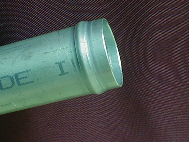
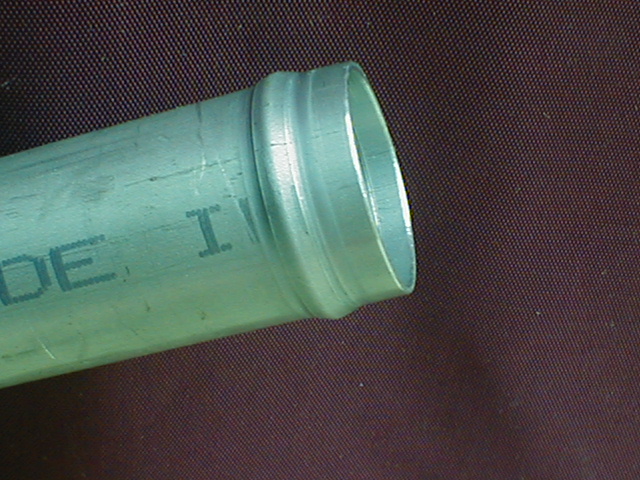
All hose barbs and other hose connections on the engine or the water pump must
have beads near the end to retain the hose.
An engineer working for Cummins Engines contacted me at OSH and told me about a
study Cummins did on the reliability of Cummins engines in over the road tractor
trailer type trucks. Cummins found that the most unreliable engine system was
the cooling system. It was the cooling hose and hose connections. They found
that the ordinary black rubber hose actually was eroding from the inside due to
differences in electrical potential and hardening over time due to heat cycling.
The solution was change the hose material used to silicone and use constant
tension hose clamps designed for soft silicone rubber hose.
Constant tension hose clamps.
Constant tension hose clamps keep a constant pressure on the hose as the
aluminum hose barbs expand and contract underneath it. They also have a
stainless steel liner that protects the soft silicon hose from destruction by
the slots in the hose clamps. Automotive black hose and fifty cent hose clamps
are not acceptable. In fact this is so important and so critical it would be
wise to use two hose clamps per connection. Several rotary powered airplanes
have crashed destroying years of work and untold amounts of money because the
builders ignored these very very important details and saved a few dollars on
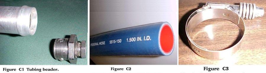
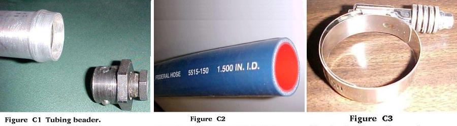
the plumbing. Fig. C1 is a tool used to form hose barbs in aluminum tubing. Next
page. This is extremely important. Do not omit this step. Hose will slip off the
tubing despite how tight the hose clamp. Fig. C2 is the proper silicone hose to
use. Fig. C3 is a Breeze constant tension hose clamp. Note the Belleville
spring washers."
In your case you don't go very fast so a thermostat is not a bad idea.
In a high speed airplane going 150 MPH or faster one throws away MPG
by using a a thermostat instead of cowl flaps.
Paul Lamar
--
The Rotary Engine NewsLetter. Powered by Linux.
ACRE NL web site.
http://www.rotaryeng.net
Youtube key word UTUBPLEASE
Copyright 1998-2008 All world wide rights reserved.