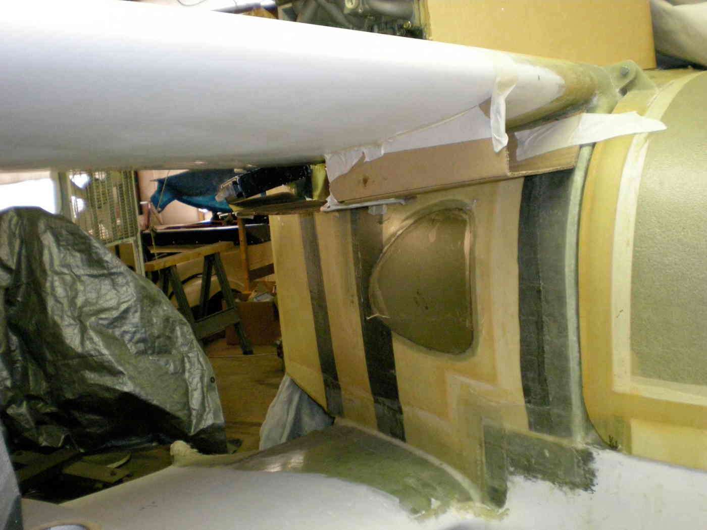
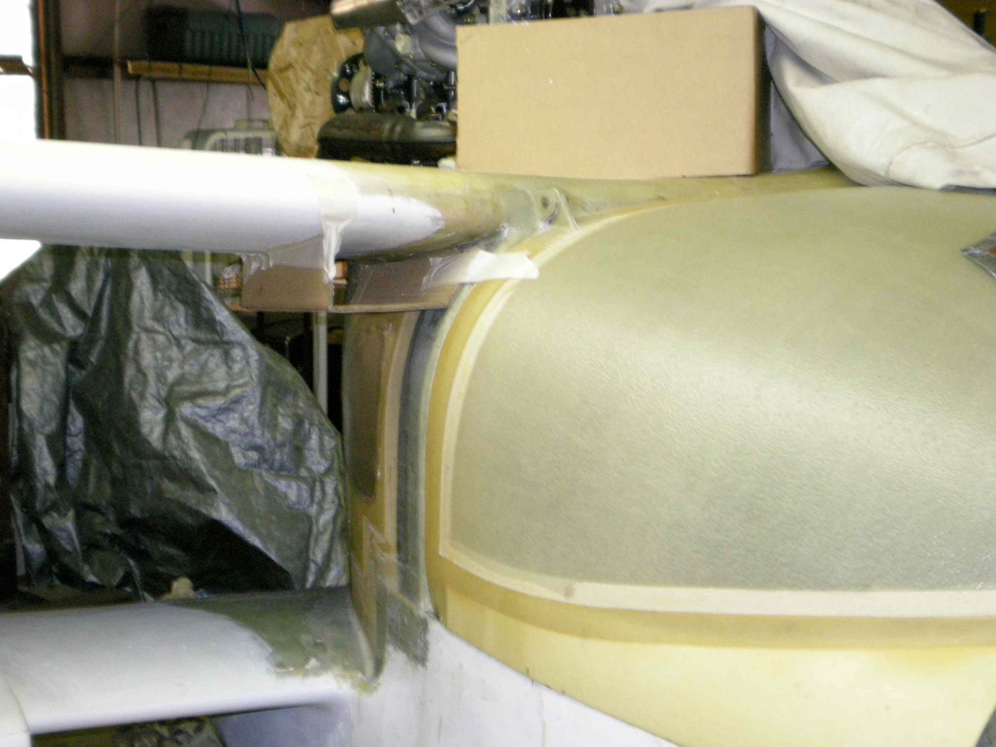
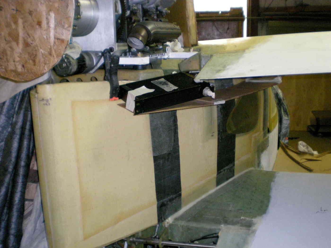
The fundamental problem with internal rads is there is not
enough room
around the engine, the wing and wing spar to get the required
ducting down through there to feed the internal mounted rads
on the
inside walls of the aft fuselage. That will become apparent
once you get the side mounted alternator and exhaust system
on the engine. The ONLY choice it to feed them with some
sort of scoops mounted between the wings on the outside
sides of the fuselage. You can make them tall and skinny or you
can make them large and round. If you make them large and round
you will intrude on the cargo space with the internal ducting
required.
Kit builders never want you to change anything :) The
original problem
goes back to the basic concept of the airplane. People are
too wide
and the distance from the back of the cockpit to the prop is
too short.
That means the sides of the fuselage go back at too sharp of
an angle.
Separation will occur. Turbulators or vortex generators mounted
on the sides of the fuselage will help mitigate but not
eliminate
the problem. The entire fuselage might work better if
totally redesigned
to the pollywog shape but that was never done. The bi plane
configuration
aggravates the situation as it constrains the flow to 2D.
IMHO I will go
out on a limb and say the only effect of the out side
mounted rads
will be an increase in frontal area and any devices now on
the sides
of the fuselage will not be necessary.
The air coming out of the proposed louvered grills will
affect the flow as well.
Perhaps you can make a half mock up and check it on the back
of a pick up
truck. I suggested that to Scott Gettings when I saw his
airplane and he may have built the full scale test mock up
all ready.
Another option is increase the length of the cowl and put
the rads
up in front of the engine. I think Rino flew his airplane
with that configuration. I don't know if it cooled or not.
This airplane holds the worlds record for ACRE volume of
cooling discussion :)
Paul Lamar
Yes I have the mockup built, with water pressure measurement
ports, etc. I haven't built the radiator/vanes or "flown" the
whole thing on top of my truck yet. I'll see if I can dig up a
picture.
This delay is because my regular job has just taken all of my
time. Maybe Sandy can come down for a weekend and we'll do the
whole thing!
Scott Gettings
Paul,
I did not extend the cowling because there is no more space up front,
extending it, it would overhang over the canopy which then could not be
opened.
Rino
Ah so. Right! I forgot. We are between a rock and a hard spot here.
Does anybody have CFD up and running?
Paul Lamar
Paul and group:
Here is one last iteration that I wonder if it might be worth
studying when I do the airflow/pressure testing on my Goose
fuselage/wing mockup:
A front radiator design (see the cardboard mockup in the first pic)
argues heavily for a pair of oil coolers somewhere else on the
plane. We are currently looking at embedding a pair of coolers in
turning vanes, or ducted beside the pylon (as per Paul's previous
postings).
A previously-considered idea was to use armpit scoops and duct air
back to coolers somewhere around the pylon. This was originally not
felt to be feasible.
The RX8 oil coolers are about 125 cu in each, which would require
about 125/2*.30 for 2" thick coolers, or about 18 sq inches of
intake area. This could be accomplished with a 6"x3" duct tucked
under each upper wing. If the duct ended in a wedge diffuser under
a cooler that was embedded in the wing root just outside the
cowling, would the top of the wing and retreating cowling give an
attractively-low pressure area on top of the cooler? Obviously,
the whole wing root and cowling interface area would have to be
blended together. One of Paul's previous drawings showed an
extended wing root.
I remember that one plane (Velocity?) did not have much luck with
under-wing ducts and upper surface air exit ducting. However, this
is just a mockup exercise.
If this might be worthwhile, I could also mock this version up and
get some pressure measurements along with the other options.
Scott Gettings
I think we can get a 12 by 12 Setrab oil cooler for the other side
and use a larger rad on just one side. Dave Leonard has had good luck
with this Setrab oil cooler. Al Gietzen finally got that 3 rotor Velocity
cooling pretty good.
http://www.rotaryeng.net/final-cut2-Al-Gietzen-Velocity.wmv
Paul Lamar
--
The Rotary Engine NewsLetter. Powered by Linux.
ACRE NL web site.
http://www.rotaryeng.net
Youtube key word UTUBPLEASE
Copyright 1998-2008 All world wide rights reserved.